Device for detecting damage depth of object surface scratch

A technology for detecting equipment and object surfaces, applied in the field of measurement, to achieve the effects of simple operation, small size and convenient reading

Inactive Publication Date: 2013-02-20
BEIJING CHANGCHENG INST OF METROLOGY & MEASUREMENT AVIATION IND CORP OF CHINA
View PDF5 Cites 6 Cited by
  • Summary
  • Abstract
  • Description
  • Claims
  • Application Information

AI Technical Summary

Problems solved by technology

[0004] The purpose of the present invention is to solve the problem of on-site quantitative detection of the surface damage depth of an object and realize the traceability of the measurement value, and propose a detection device for the damage depth of the object surface

Method used


Image

  • Device for detecting damage depth of object surface scratch
  • Device for detecting damage depth of object surface scratch
  • Device for detecting damage depth of object surface scratch

Examples


Embodiment 1

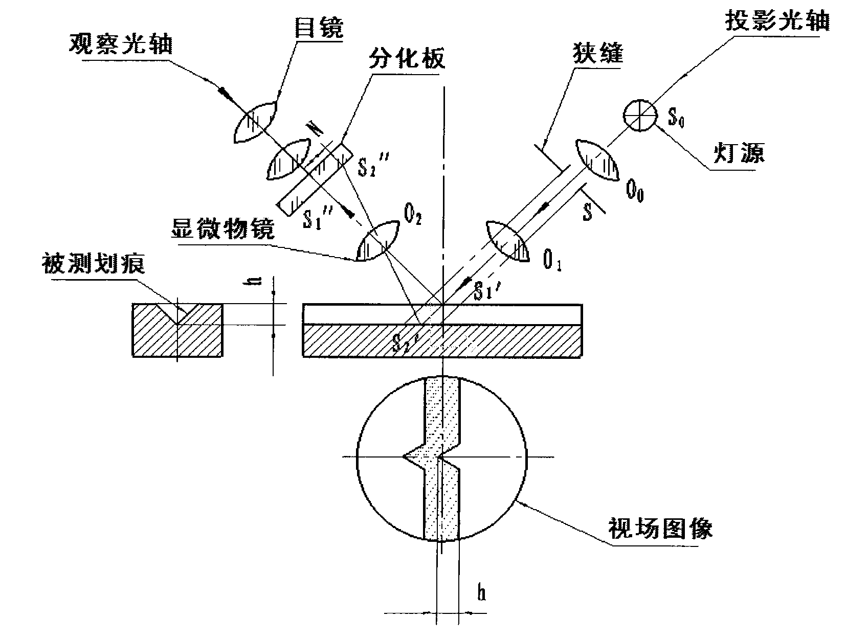
[0038] This embodiment is to use the detection device of the present invention for the detection of the depth of scratches on the surface of a military aircraft cockpit. It works in the eyepiece observation mode, and its optical measurement principle diagram is as follows figure 1 As shown, the light source S0 is placed in the projection light mirror O 0 on the focus, by S 0 The light emitted by O 0 Finally, a beam of parallel light is obtained, and the parallel light passes through the slit S to form a narrow parallel beam; the beam is projected through the objective lens O 1 Convergence, projected onto the measured surface of the part in a 45° direction to form a light section; the existence of scratches makes the measured surface of the part have tiny peaks and valleys, and the peak is in S 1 ′ point produces reflection, and the trough is at S 2 ' produces reflections (where S 1 'The point is exactly O 1 and O 2 common focus), then the reflected light passes through t...

Embodiment 2

[0044] This embodiment is that the detection equipment of the present invention is used for a kind of military aircraft skin surface scratch depth detection, works under the CCD observation mode, and its optical schematic diagram is as follows Figure 4 As shown, the light source S 0 placed in the projection light mirror O 0 on the focus, by S 0 The light emitted by O 0 Finally, a beam of parallel light is obtained, and the parallel light passes through the slit S to form a narrow parallel beam; the beam is projected through the objective lens O 1 Convergence, projected onto the measured surface of the part in a 45° direction to form a light section; the existence of scratches makes the measured surface of the part have tiny peaks and valleys, and the peak is in S 1 ′ point produces reflection, and the trough is at S 2 ' produces reflections (where S 1 'The point is exactly O 1 and O 2 common focus), then the reflected light passes through the observation objective lens...


PUM


Abstract

The invention relates to a device for detecting damage depth of an object surface scratch and belongs to the technical field of measurement. The device for detecting the damage depth of the object surface scratch comprises an illuminating system, an observing system, an imaging system, a mechanical system and a data processing system. Working steps include stable arrangement of the detecting device, confirmation of observing direction, adjustment of an image to be observed and acquisition and quantitative analysis of the image. The device can quantitatively measure the depth of the object surface scratch and measure the depth value of 0.002mm of micro damage, adopts non-contact measurement, and does not produce secondary damage to a measured object. A measurement value can trace to the source, the detecting device is small in volume, convenient to read and simple in operation, and an adopted ball head support screw is suitable for object surfaces with various shapes. The device for detecting the damage depth of the object surface scratch is suitable for field inspection of local damage of large parts.

Description

technical field [0001] The invention relates to a detection device for the depth of scratch damage on the surface of an object, which belongs to the field of measurement technology. Background technique [0002] At present, the on-site detection of the surface damage depth of various types of objects such as the glass surface of the aircraft cockpit, the surface of the aircraft skin, the outer surface of the engine pipeline, the surface of the cold-worked plate, the surface of the precision casting and the surface of the main shaft of the EMU is a technical problem that needs to be solved urgently. On-site quantitative detection of surface scratch depth is an important basis for judging the degree of damage to parts. [0003] The current similar techniques for measuring the depth of damage include: the copying method, the stylus method, and the focusing depth-of-field method. The copying method is to use silica gel to turn the damaged part into a positive mold, and then mea...

Claims


Application Information

Patent Timeline
Patent Type & Authority Applications(China)
IPC IPC(8): G01B11/22
Inventor 马晓苏瞿剑苏陆佳艳王霁张文军
Owner BEIJING CHANGCHENG INST OF METROLOGY & MEASUREMENT AVIATION IND CORP OF CHINA
Why Eureka
Try Eureka