Method for tightening screw connections

A technology for tightening screws and screws, which can be used in screwdrivers, rails, rail maintenance, etc., and can solve different problems

Active Publication Date: 2015-03-04
ROBEL BAHNBAUMASCH
View PDF10 Cites 0 Cited by
  • Summary
  • Abstract
  • Description
  • Claims
  • Application Information

AI Technical Summary

Problems solved by technology

However, this type of screw-tightening operation leads to the disadvantage that the actual effective pressing force for connecting the sleeper to the rail differs depending on the coefficient of friction, even if the respective tightening torque remains constant

Method used


Image

  • Method for tightening screw connections
  • Method for tightening screw connections
  • Method for tightening screw connections

Examples


Embodiment Construction

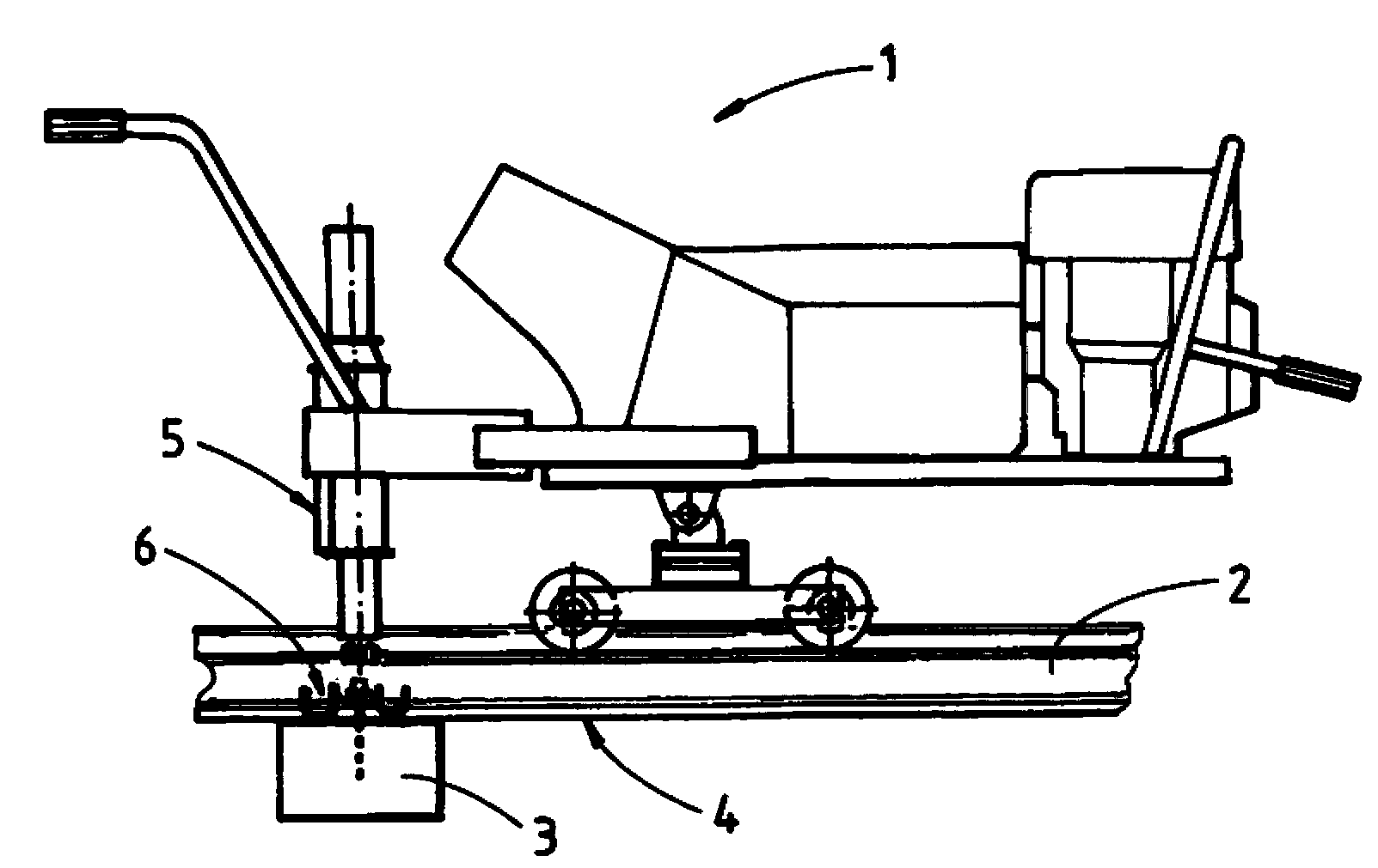
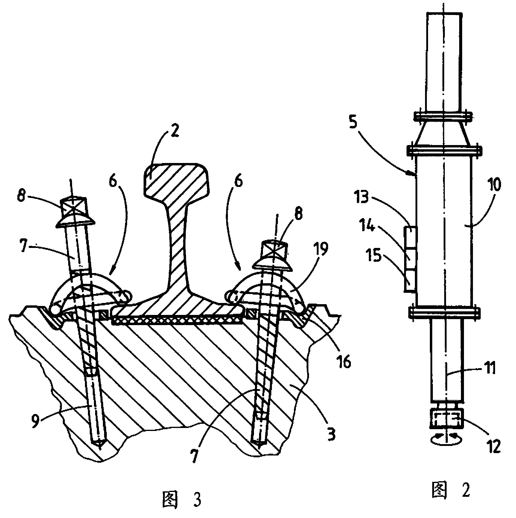
[0009] figure 1 The screw tightening machine 1 seen in is movable on a rail 4 formed by rails 2 and sleepers 3 and is equipped with a vertically adjustable servo screw drive 5 . These parts are used for fastening screw connections 6, according to image 3 In the example shown in more detail, the screw connection comprises a screw 7 with a screw head 8 and a screw hole 9 on the sleeper 3 .

[0010] From figure 2 It can be seen that each servo screw driver 5 has a servo motor 10 and a wrench 12 rotatable about an axis 11 . Furthermore, a processor 13 equipped with a data memory is connected to a rotation angle measurer 14 and a torque sensor 15 .

[0011] Such as image 3 It can be seen that the spring clip-shaped fastening device 19 is arranged between the rail head 8 and the base plate 16 on the sleeper 3 . The spring clips are in contact with the base plate 16 and the rail 2 .

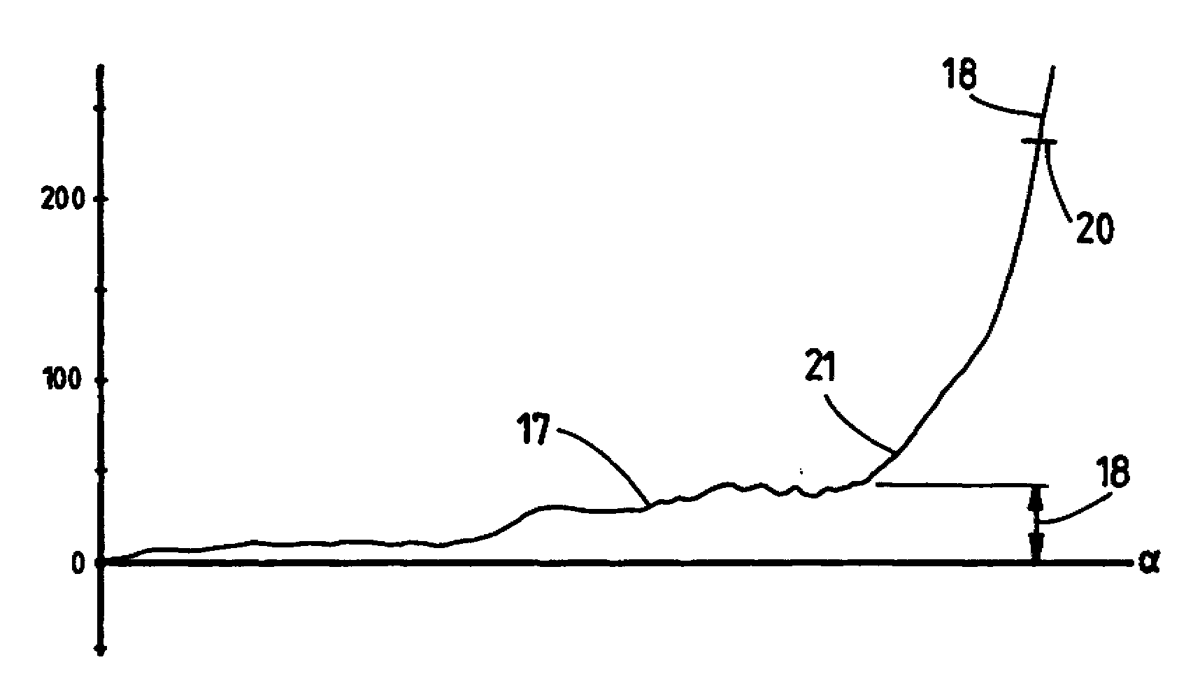
[0012] Starting from the starting position shown in the left half of the figure, the screw ...


PUM


Abstract

In order to tighten screw connections, a screw-in torque (17) which is effective during the screwing in of a screw is sensed and a compensation value (18) which is dependent thereon is determined, and the setpoint torque (20) is increased as a function of the previously determined compensation value (18) for the complete tightening of the screw (7).

Description

technical field [0001] The present invention relates to a method of tightening screw connections using a power-driven wrench by obtaining a defined target torque. Background technique [0002] From DE 1708657 is known a device for tightening sleeper screws with a tightening torque independent of the screw tightening torque. However, this type of screw-tightening operation entails the disadvantage that the actual effective pressing force connecting the sleeper to the rail differs depending on the coefficient of friction, even if the respective tightening torque remains constant. The different coefficients of friction are, for example, the result of uneven conditions on the thread surface. Contents of the invention [0003] The object of the invention is to provide a method of the aforementioned type which ensures a constant pressing force for all screw connections. [0004] According to the invention, this object is achieved by a method of a certain kind, which detects th...

Claims


Application Information

Patent Timeline
Patent Type & Authority Patents(China)
IPC IPC(8): E01B29/28B23P19/06B25B23/14
CPCE01B29/28B25B23/14B23P19/066
Inventor O.威德尔罗伊瑟
Owner ROBEL BAHNBAUMASCH
Why Eureka
Try Eureka