Separating type stuffing box

A stuffing box, separate technology, applied in the direction of valve details, engine components, shaft seals, etc., can solve the problems of increasing the difficulty of processing and installation, affecting the sealing performance of stuffing box, and damage to V-shaped packing, so as to achieve simple structure, reduce Effect of small size and reduced processing difficulty

Inactive Publication Date: 2014-12-03
CHONGQING CHUANWU INSTR
View PDF0 Cites 0 Cited by
  • Summary
  • Abstract
  • Description
  • Claims
  • Application Information

AI Technical Summary

Problems solved by technology

The shortcomings of the above structure are 1. Since the stuffing box and the upper valve cover are integrated, the overall size is large, which increases the difficulty of processing and installation; 2. When installing the V-shaped packing, the operator needs to face the opening direction of the V-shaped packing. When lowering, install the entire V-shaped packing from top to bottom into the upper bonnet packing cavity, which will easily cause damage to the V-shaped packing during installation, thus affecting the sealing performance of the stuffing box

Method used


Image

  • Separating type stuffing box

Examples


Embodiment 1

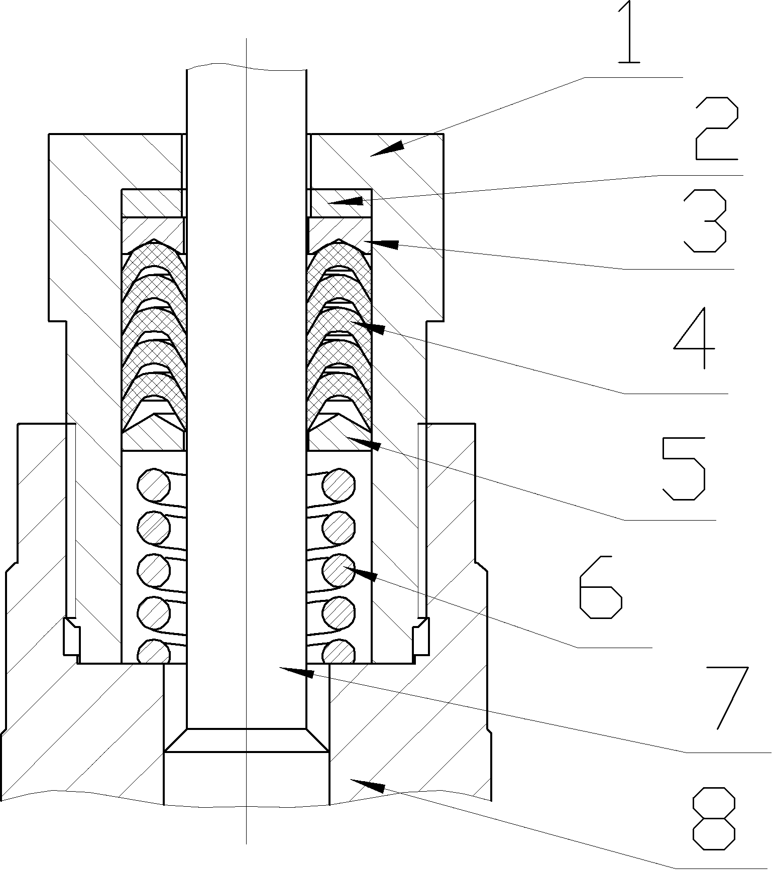
[0017] like figure 1 As shown, the separate stuffing box includes a hollow box body 1 with the opening facing down and a V-shaped packing 4 located in the stuffing chamber of box body 1, and also includes a packing gland on box body 1, and the stuffing gland and box body 1 is integrated, which is convenient for processing. The upper valve cover 8 is provided with a chamber that can accommodate the box body 1. The lower end surface of the box body 1 is closely attached to the bottom surface of the upper valve cover 8 chamber. The gap between the box body 1 and the upper valve cover 8 Threaded connection; the valve stem 7 passes through the packing gland, spacer 2, upper bushing 3, V-shaped packing 4 and lower bushing 5; the upper and lower sides of the V-shaped packing 4 in the box are respectively equipped with an upper bushing 3 and a lower bushing 5 , the lower part of the upper bushing 3 is provided with a V-shaped groove for fixing the V-shaped packing 4, and the lower bus...

Embodiment 2

[0020] The difference from the first embodiment is that the packing gland and the box body are connected by bolts.


PUM


Abstract

The invention discloses a separating type stuffing box comprising a hollow box body with an opening facing toward an upper bonnet, V-shaped fillers in the box body and a filler gland arranged on the box body. The upper bonnet is provided with a chamber accommodating the box body. The bottom face, of the lower end of the opening of the box body, is closely attached to the bottom face of the chamber of the upper bonnet. The box body is detachably connected with the upper bonnet. The separating type stuffing box is simple in structure, handy and practical.

Description

technical field [0001] The invention relates to the technical field of stuffing boxes for valves, in particular to a separate stuffing box. Background technique [0002] The valve is a control component in the fluid delivery system, which has functions such as cut-off, adjustment, flow diversion, reverse flow prevention, pressure stabilization, flow diversion or overflow pressure relief. Valves used in fluid control systems range from the simplest cut-off valves to various valves used in extremely complex automatic control systems, with a wide variety of varieties and specifications. Valves can be used to control the flow of various types of fluids such as air, water, steam, various corrosive media, mud, oil, liquid metal and radioactive media. Valves are also divided into cast iron valves, cast steel valves, stainless steel valves (201, 304, 316, etc.), chrome-molybdenum steel valves, chrome-molybdenum-vanadium steel valves, duplex steel valves, plastic valves, non-standar...

Claims


Application Information

Patent Timeline
Patent Type & Authority Applications(China)
IPC IPC(8): F16K41/02
CPCF16K41/04F16K41/06
Inventor 蔡杰浩
Owner CHONGQING CHUANWU INSTR
Why Eureka
Try Eureka