Manufacturing method of locking ring and used fixtures

A manufacturing method and lock ring technology, applied in the field of aero-engine, can solve the problems of flat steel wire winding lock ring easily deformed, unable to be tightly wound and shaped, etc., to achieve good elasticity and adaptability, ensure flatness requirements, and ensure the effect of assembly requirements

Inactive Publication Date: 2013-02-27
SHENYANG LIMING AERO-ENGINE GROUP CORPORATION
View PDF5 Cites 1 Cited by
  • Summary
  • Abstract
  • Description
  • Claims
  • Application Information

AI Technical Summary

Problems solved by technology

[0003] Aiming at the problems existing in the prior art, the present invention provides a method for manufacturing the lock ring and the clamp used. The manufacturing method and the clamp used successfully solve the technical problems that the lock ring is easily deformed and cannot be tightly wound and shaped when the flat steel wire is used. Guaranteed the size requirements of the lock ring

Method used


Image

  • Manufacturing method of locking ring and used fixtures
  • Manufacturing method of locking ring and used fixtures
  • Manufacturing method of locking ring and used fixtures

Examples


Embodiment Construction

[0033] The present invention will be further described in detail below in conjunction with the accompanying drawings and specific embodiments.

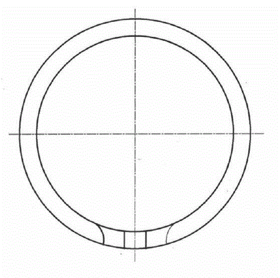
[0034] A method for manufacturing a locking ring, specifically comprising the steps of:

[0035] Step 1: Raw material preparation

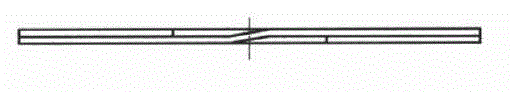
[0036] Prepare the 6mm×1mm, GH4169 flat steel wire that needs to be wound for use;

[0037] Step 2: Winding preparation

[0038] Install and fix the special auxiliary fixture for lock ring winding, fix the base 1 of the special auxiliary fixture for lock ring winding on the tool holder of the lathe, pass the flat steel wire through the rectangular groove 4 on the inner roller 3, and set it aside;

[0039] Step 3: Wrap the flat steel wire

[0040] Fix the end of the mandrel 7 without the rectangular thread groove 12 of the special rectangular thread groove winding fixture for the lock ring on the three-jaw chuck of the lathe, and pass through the flat of the special auxiliary fixture for lock ring windi...


PUM


Abstract

The invention relates to a manufacturing method of a locking ring and used fixtures, which belong to the technical field of aircraft engines. By using the manufacturing method and the used fixtures, the technical problems of easiness in deformation and difficulty in tight winding and forming due to the fact that a flat wire is used for winding the locking ring are successfully solved. The manufacturing method has the technical scheme that the manufacturing method of the locking ring comprises the following steps of preparation of raw materials, preparation of winding, winding of the flat wire, forming of the locking ring and heat treatment for forming. An auxiliary winding fixture special for the locking ring comprises a base, wherein a shell is arranged on the base, and an outer roller and an inner roller are arranged in the shell. A rectangular thread slot winding fixture special for the locking ring comprises a core rod, wherein a core rod step is arranged on the core rod, a step rectangular slot is formed in the core rod step, a bolt is arranged on one side of the step rectangular slot, and a washer is arranged between the bolt and the core rod step. A forming fixture special for the locking ring comprises a forming base, wherein an inner step is arranged inside the forming base, and a pressure plate is arranged above the forming base.

Description

technical field [0001] The invention belongs to the technical field of aero-engines, and in particular relates to a method for manufacturing a locking ring and a clamp used therefor. Background technique [0002] Such as figure 1 , figure 2 As shown, the general lock ring is formed by winding flat steel wires. Since the flat steel wires have a wider cross-section and greater stress, they are prone to deformation. Such as image 3 , Figure 4 As shown, when the flat steel wire is bent and wound on the basis of the thickness surface, the winding angle is relatively large, and the deformation stress is also large. The outer side of the flat steel wire is subjected to tensile stress and the inner side is subjected to compressive stress. That is, the outside has a tendency to bend upwards or downwards. Contents of the invention [0003] Aiming at the problems existing in the prior art, the present invention provides a method for manufacturing the lock ring and the clamp u...

Claims


Application Information

Patent Timeline
Patent Type & Authority Applications(China)
IPC IPC(8): B21F37/00
Inventor 崔媛尚作义张奇刘永赵智
Owner SHENYANG LIMING AERO-ENGINE GROUP CORPORATION
Why Eureka
Try Eureka