
Variable frequency hydraulic coupling cable drum

A cable reel and hydraulic coupling technology, applied in the field of power supply devices for mobile equipment, can solve the problems of unsatisfactory effect, shorten the service life of the cable, damage to the cable sheath, etc., to solve the problem of rapid response, prolong the service life, Low maintenance effect

Active Publication Date: 2015-04-15
YUEYANG HAIRUN ELECTRIC
View PDF8 Cites 0 Cited by
  • Summary
  • Abstract
  • Description
  • Claims
  • Application Information

AI Technical Summary

Problems solved by technology

In general, the running distance of the quay crane is relatively large, ranging from 200 meters to 400 meters. Since the reel requires more cable capacity, the D1 and D2 of the reel are relatively large. During the process of reeling and unwinding the cable, The tension of the cable fluctuates greatly, which will easily damage the cable sheath and greatly reduce the service life of the cable. In response to this situation, the supplier usually improves the multi-head drive hysteresis cable reel and adopts the form of section protection. , that is, different numbers of driving heads are opened at different stages to reduce the tension on the cable when the reel is unwound. Although the control and manufacturing are more complicated, the effect is still not satisfactory
[0003] With the development of the economy, reliability, safety and efficiency have become the underlying requirements of the logistics industry. The characteristics of the field bridge (RTG) are large power supply current, good rigidity of the reel, large moment of inertia, high acceleration, and fast speed (up to 120m / min). , The vector frequency conversion speed regulation cable reel can no longer meet this requirement very well. Due to the acceleration requirement, in terms of response speed, the frequency conversion speed regulation reel usually has to reduce the energy efficiency, which can be barely solved by using a large horse-drawn car, but The protection of the cable is still very lacking

Method used


Image

  • Variable frequency hydraulic coupling cable drum
  • Variable frequency hydraulic coupling cable drum
  • Variable frequency hydraulic coupling cable drum

Examples


Embodiment Construction

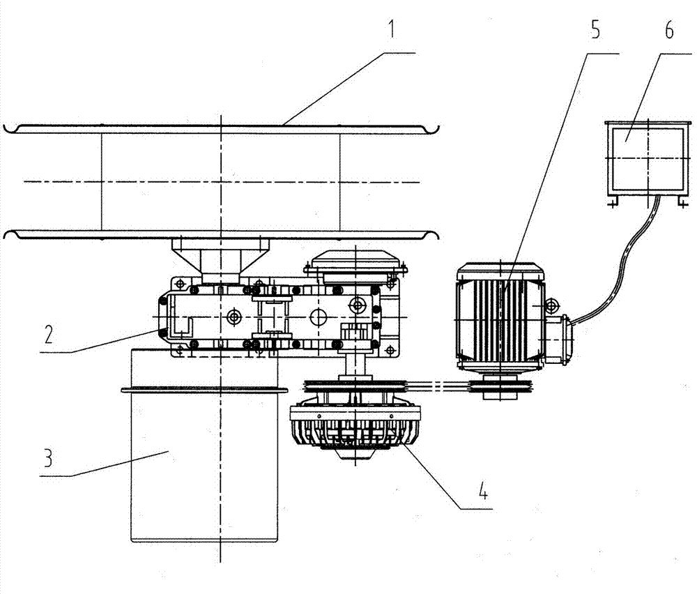
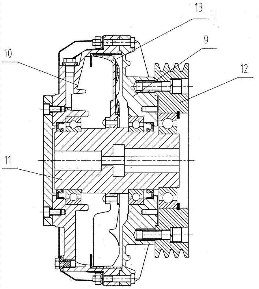
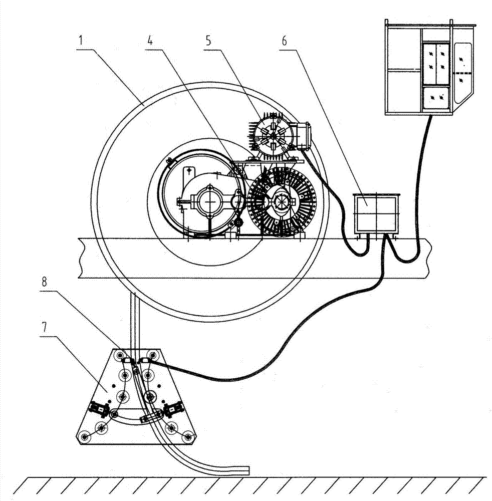
[0017] Depend on Figures 1 to 3 It can be seen that the present invention includes a cable reel body 1, a cable guide 7 arranged on the cable reel of a mobile device, and a drive system for driving the action of the cable reel body 1. The drive system is composed of a headstock 2, a hydraulic A flexible drive system composed of a coupler 4 and a variable frequency electrical controller 6, wherein:

[0018] The hydraulic coupling 4 is connected to the drive motor 5 through a belt or a rigid coupling, and the drive motor 5 is connected to the frequency conversion electrical controller 6 through a conductor, and the frequency conversion electrical controller 6 is connected to and receives signals from the fairlead 7 and the command center and converts them into electrical signals. The frequency is transmitted to the drive motor 5 through the conductor. The drive motor 5 receives the electric frequency and generates a corresponding speed to drive the fluid coupling 4 to rotate. T...


PUM


Abstract

The invention relates to a variable frequency hydraulic coupling cable drum which comprises a cable drum body, a cable guide rack and a driving system, wherein the driving system is a flexible driving system formed by a spindle box, a hydraulic coupler and a variable frequency electrical controller; the hydraulic coupler is connected with a driving motor by a belt or a rigid coupler; the driving motor is connected with the variable frequency electrical controller by a conductor; the variable frequency electrical controller is used for connecting and receiving signals of the cable guide rack and a command center, converting the signals into electrical frequency and transmitting the electrical frequency to the driving motor by the conductor; the driving motor is used for receiving the electrical frequency and generating corresponding speed to drive the hydraulic coupler to rotate; the hydraulic coupler is used for transmitting flexible torque to the spindle box by an output shaft connected with the spindle box; the spindle box is connected with the cable drum body and is used for driving the cable drum body to rotate synchronously along with a cable drum arranged on a mobile device for taking-up or paying-off a cable. The variable frequency hydraulic coupling cable drum adopts the high-slip hydraulic coupler and a variable frequency speed controller as the driving system of the cable drum, thus solving the problems of taking-up or paying-off the cable of the cable drum; and the variable frequency hydraulic coupling cable drum is simple in structure and convenient to install and maintain.

Description

technical field [0001] The invention relates to a power supply device for mobile equipment, in particular to a variable frequency hydraulic coupling cable reel. Background technique [0002] At present, the power supply of high-end cranes such as port quay cranes and field bridges mostly uses multi-head drive hysteresis cable reels such as image 3 Or frequency conversion speed regulation cable reel such as Figure 4 , the arrangement of the cables on the reel is generally a single layer, such as image 3 and Figure 4 in the reel. In general, the running distance of the quay crane is relatively large, ranging from 200 meters to 400 meters. Since the reel requires more cable capacity, the D1 and D2 of the reel are relatively large. During the process of reeling and unwinding the cable, The tension of the cable fluctuates greatly, which will easily damage the cable sheath and greatly reduce the service life of the cable. In response to this situation, the supplier usually i...

Claims


Application Information

Patent Timeline
Patent Type & Authority Patents(China)
IPC IPC(8): B65H75/38B65H75/42B65H75/44
Inventor 刘彬刘剑
Owner YUEYANG HAIRUN ELECTRIC
Learn More