Multistage distributed water pump heat supply system and design method thereof

A heating system, distributed technology, applied in heating systems, hot water central heating systems, household heating, etc., can solve the problems of mutual coupling of hydraulic conditions, damage to the hydraulic balance of heat users, and large diameter of the pressure equalizing tank.

Inactive Publication Date: 2013-02-27
HARBIN INST OF TECH +1
View PDF4 Cites 14 Cited by
  • Summary
  • Abstract
  • Description
  • Claims
  • Application Information

AI Technical Summary

Problems solved by technology

[0028] The purpose of the present invention is to solve the problem of large ineffective energy consumption and mutual coupling of hydraulic working conditions in the traditional direct-connected central heating system; to solve the mutual coupling of hydraulic working conditions of the distributed frequency conversion water pump system, which cannot meet the requirements of system expansion or load changes Requirements, the problem that the hydraulic balance of the heat user before the zero pressure difference point is destroyed; in order to solve the problem of large ineffective energy consumption and large diameter of the pressure equalizing tank in the heating system using the pressure equalizing tank, and then provide a multi-stage Distributed water pump heating system and its design method

Method used


Image

  • Multistage distributed water pump heat supply system and design method thereof
  • Multistage distributed water pump heat supply system and design method thereof
  • Multistage distributed water pump heat supply system and design method thereof

Examples


specific Embodiment approach 1

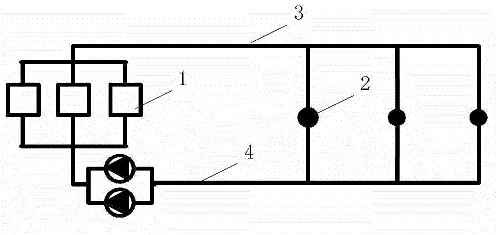
[0105] Specific implementation mode one: combine Figure 9 Describe this embodiment. The multi-stage distributed water pump heating system of this embodiment includes a heat source 1, a circulating water pump group 2 at the heat source, a water supply pipeline 7, a return water pipeline 8, and N-level distribution stations, each of which includes decoupling pipes 4. Grading booster pump 6. At least one set of secondary network loops; each set of secondary network loops is composed of heat user booster pump 3 and at least one heat user 5, heat source 1, circulating water pump group 2 at the heat source, water supply pipeline 7 and the return water pipeline 8 form the total heat supply circulation loop of the heating network, and a multi-level distribution station is arranged between the water supply pipeline 7 and the return water pipeline 8; the decoupling pipes 4 of the multi-level distribution stations are arranged in parallel, and each decoupling pipe 4 One end of each deco...

specific Embodiment approach 2

[0108] Specific implementation mode two: combination Figure 9 To describe this embodiment, the diameter of each decoupling pipe 4 in this embodiment is smaller than or equal to the diameter of the water supply pipeline 7 or the return water pipeline 8 . In this embodiment, the diameter of the decoupling pipe is less than or equal to the maximum diameter of the connecting pipe, so that the required installation space is small, the manufacturing cost is low, it is easy to manufacture and install, and can meet the needs of actual heating. Others are the same as the first embodiment.

specific Embodiment approach 3

[0109] Specific implementation mode three: combination Figure 9 To describe this embodiment, the diameter of each decoupling pipe 4 in this embodiment is larger than the diameter of the water supply pipeline 7 or the water return pipeline 8 . In this embodiment, the diameter of the decoupling pipe is larger than the maximum diameter of the connected pipes, so it is easy to meet the strength requirements of the decoupling pipe, easy to manufacture and install, and can meet the needs of actual heating. Others are the same as the first embodiment.


PUM


Abstract

A multistage distributed water pump heat supply system and a design method thereof relate to a heat supply system and the design method thereof. The system and the method aim at resolving the problem that a traditional direct connection type central heating system is large in ineffective energy consumption, hydraulic power work conditions are mutually coupled, hydraulic power work conditions of a distributed frequency conversion water pump system are coupled and cannot meet the requirement for system extension or load change, balance of hydraulic power of heat users before zero-pressure different point is damaged, and the existing heat supply system adopting a voltage sharing tank is large in ineffective energy consumption and large in voltage sharing tank diameter. The multistage distributed water pump heat supply system comprises a heat source, a heat source position circulation water pump unit, a water supply pipe, a water return pipe and a multistage distribution station. Each-stage distribution station comprises a decoupling tube, a classification pressurization pump and at least one secondary net loop. Each secondary net loop is composed of a heat user pressurization pump and at least one heat user. Decoupling pipes of the multi-stage distribution station are arranged in parallel. The multistage distributed water pump heat supply system is used for centralized heat supply.

Description

technical field [0001] The invention relates to a heating system and a design method thereof, in particular to a multi-stage distributed centralized heating system and a design method thereof. Background technique [0002] my country's building energy consumption has reached about 1 / 4 of the country's total energy consumption, and will gradually increase with the improvement of people's living standards. About 36% of building energy consumption is heating energy consumption in northern cities and towns. [0003] At present, most cities and towns in northern my country use thermal power plants or boiler rooms as heat sources for centralized heating systems to solve building heating problems. A complete heating system is composed of three parts: the heat source that converts the energy in the fuel into heat energy, the transmission and distribution system that transmits the heat produced by the heat source to the users who need heat, and the heat users who consume heat. The ...

Claims


Application Information

Patent Timeline
Patent Type & Authority Applications(China)
IPC IPC(8): F24D3/02F24D3/10
Inventor 方修睦刘成周志刚
Owner HARBIN INST OF TECH
Why Eureka
Try Eureka