Distributed water mixing and pressurized heat supply system having decoupling function and design method of system

A heating system, distributed technology, applied in the direction of heating systems, hot water central heating systems, lighting and heating equipment, etc., can solve the problem of mutual coupling of hydraulic conditions, inefficient energy consumption, large ineffective energy consumption, and pressure equalization tank diameter major issues

Inactive Publication Date: 2013-03-13
HARBIN INST OF TECH +1
View PDF5 Cites 13 Cited by
  • Summary
  • Abstract
  • Description
  • Claims
  • Application Information

AI Technical Summary

Problems solved by technology

[0035] The purpose of the present invention is to provide a distributed water mixing and pressurized heating system with decoupling function and its design method to solve the problem of large ineffective energy consumption and mutual coupling of hydraulic working conditions in the traditional direct-connected central heating system problems; solve the problem of mutual coupling of hydraulic working conditions and poor system adaptability of the distributed pump system; solve the problem of mutual coupling of hydraulic working conditions of the conventional mixing system and the existence of invalid energy consumption; solve the problem of large invalid energy consumption and pressure equalization of the equalizing tank system Problems with large tank diameters

Method used


Image

  • Distributed water mixing and pressurized heat supply system having decoupling function and design method of system
  • Distributed water mixing and pressurized heat supply system having decoupling function and design method of system
  • Distributed water mixing and pressurized heat supply system having decoupling function and design method of system

Examples


specific Embodiment approach 1

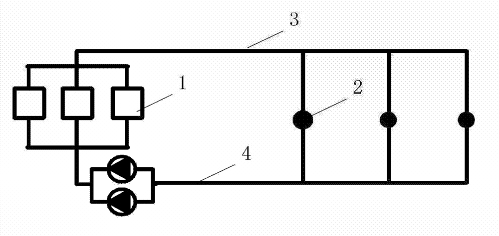
[0089] Specific implementation mode one: combine Figure 11 and Figure 12 To illustrate this embodiment, the system described in this embodiment includes a heat source 1, a circulating pump group 2 at the heat source, a primary network water supply pipe 9, a primary network return water pipe 10, a group of first heating network users 5-1, a group of first Two heating network users 5-2, a group of third heating network users 5-3, multiple first mixing water pumps 7-1, multiple second mixing water pumps 7-2, multiple third mixing water pumps 7-3, multiple A self-supporting differential pressure valve 8, a plurality of booster pumps 3, a plurality of decoupling pipes 4, a plurality of check valves 6, a plurality of first heat user inlet pipes 9-1, and a plurality of first heat user outlet pipes 10 -1. Multiple second heat user inlet pipes 9-2, multiple second heat user outlet pipes 10-2, multiple third heat user inlet pipes 9-3 and multiple third heat user outlet pipes 10-3 , ...

specific Embodiment approach 2

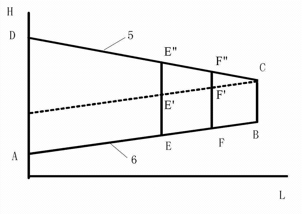
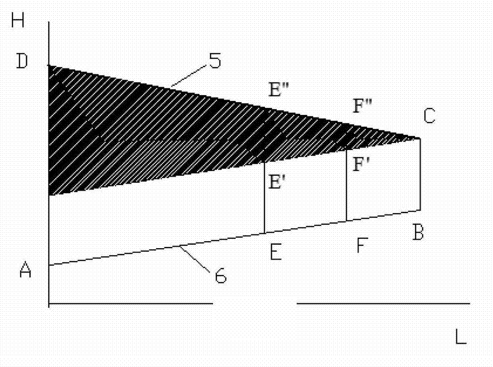
[0097] Specific implementation mode two: combination Figure 11 To illustrate this embodiment, the resource pressure head provided by the heating network in this embodiment is greater than the resource pressure head required by each first heating network user 5-1. Other implementation manners are the same as the specific implementation manner 1.

specific Embodiment approach 3

[0098] Specific implementation mode three: combination Figure 11 To illustrate this embodiment, the resource pressure head provided by the heating network in this embodiment is smaller than the resource pressure head required by each second heating network user 5-2. Other implementation manners are the same as the specific implementation manner 1.


PUM


Abstract

The invention discloses a distributed water mixing and pressurized heat supply system having a decoupling function and a design method of the system, relate to a heat supply system and a design method thereof, and aims to solve the problems of high invalid energy consumption and mutual coupling of hydraulic regimes existing in the conventional directly-connected centralized heat supply system, the problems of mutual coupling of hydraulic regimes and poor system adaptability existing in a distributed pump system, the problems of mutual coupling of hydraulic regimes and the presence of invalid energy consumption existing in the conventional water mixing system, and the problems of high invalid energy consumption and large diameter of an equalizer tank existing in an equalizer tank system. The distributed water mixing and pressurized heat supply system comprises a heat source, a heat source circulating water pump set, a water supply pipeline, a water return pipeline and three types of heat users, wherein the inlets of a first type of heat supply network users are provided with water mixing pumps and differential pressure valves; the inlets of a second type of heat supply network users are provided with water mixing pumps, booster pumps and decoupling equipment; and the inlets of a third type of heat supply network users are provided with water mixing pumps. The distributed water mixing and pressurized heat supply system is applied to heat supply systems.

Description

technical field [0001] The invention relates to a heating system and a design method thereof. Background technique [0002] my country's building energy consumption has reached about 1 / 4 of the country's total energy consumption, and will gradually increase with the improvement of people's living standards. About 36% of building energy consumption is heating energy consumption in northern cities and towns. [0003] At present, most cities and towns in northern my country use thermal power plants or boiler rooms as heat sources for centralized heating systems to solve building heating problems. A complete heating system is composed of three parts: the heat source that converts the energy in the fuel into heat energy, the transmission and distribution system that transmits the heat produced by the heat source to the users who need heat, and the heat users who consume heat. The transmission and distribution system is an important link connecting heat sources and heat users. ...

Claims


Application Information

Patent Timeline
Patent Type & Authority Applications(China)
IPC IPC(8): F24D3/02F24D3/10F24D19/10
Inventor 方修睦周志刚刘成李浩然
Owner HARBIN INST OF TECH
Why Eureka
Try Eureka