Automatic sealing machine

A technology of automatic sealing machine and frame, which is applied in the direction of bottling machines, bottle filling, flanged bottle caps, etc., which can solve the problems of heavy replacement and maintenance workload, reduced labor intensity, low efficiency, etc., to reduce maintenance costs and The effect of reducing the workload, improving the safety of use, and increasing the degree of automation

Active Publication Date: 2014-07-16
中瑞华特(济南)消防科技有限公司
View PDF10 Cites 8 Cited by
  • Summary
  • Abstract
  • Description
  • Claims
  • Application Information

AI Technical Summary

Problems solved by technology

[0002] At present, there are sealing devices for open tinplate containers in the domestic market, including manual sealing machines, semi-automatic sealing machines and automatic sealing machines; manual sealing machines are labor-intensive and inefficient, and cannot be used with automatic filling lines; semi-automatic sealing machines The labor intensity is reduced, the efficiency is not high, and the speed of the multi-head filling line cannot be kept up; the automatic sealing machine has the following main disadvantages: 1. The applicable container is single, and it is inconvenient to replace and adjust containers of different heights and diameters; 2. Currently, the capping head is manual. The sealing pliers of the sealing machine, the lowering of the cap is completed by a cylinder. After the lowering, the capping positioning plate contacts the upper plane of the container and is blocked from positioning. After the pressure of the cylinder overcomes the resistance, the capping arm bends the flower basket claws to buckle inward to realize the sealing. During the whole process, the bottom of the container is used as the support point. If the conveying line does not stop during sealing, the operating load is super strong, the power of the transmission motor is large, the surface of the transmission belt is easy to wear and tear, the replacement and maintenance workload is large, and the use and maintenance cost is high.
If the conveying line is stopped during sealing, the wear on the surface of the transmission belt is relatively small, and it needs to be started frequently before and after sealing, the production capacity is not high, and the production capacity of multi-head filling is even lower, which requires multiple heads to achieve, and the total power consumption is large.

Method used


Image

  • Automatic sealing machine
  • Automatic sealing machine

Examples


Embodiment Construction

[0014] The present invention will be described in detail below in conjunction with the accompanying drawings. The description in this part is only exemplary and explanatory, and should not have any limiting effect on the protection scope of the present invention.

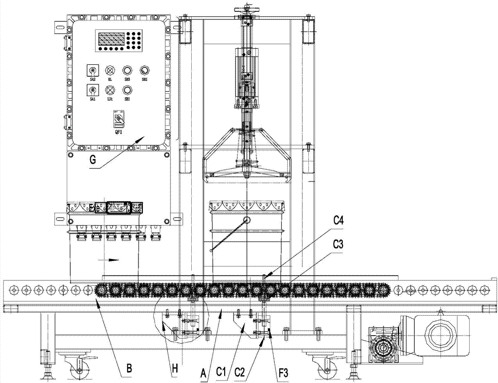
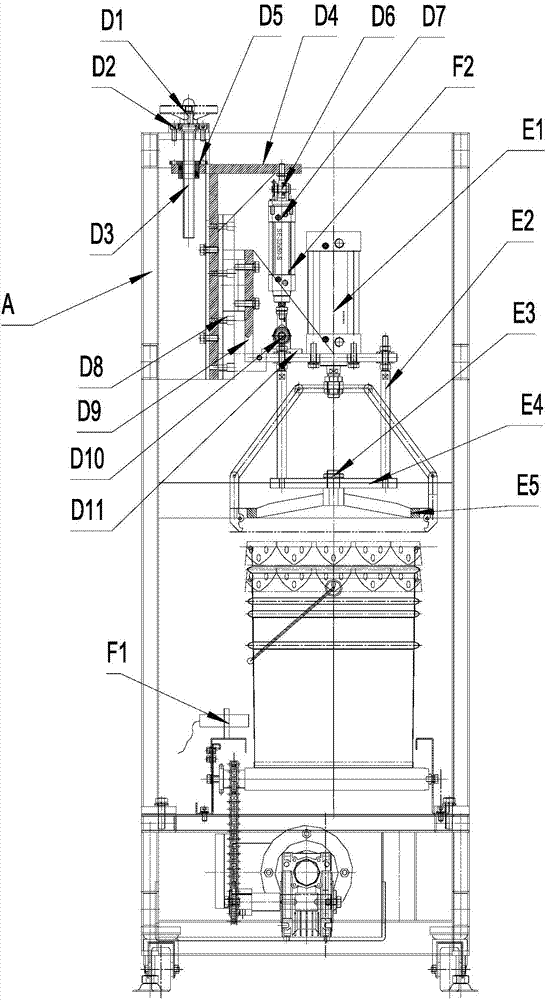
[0015] like figure 1 and 2 The automatic sealing machine shown is composed of a frame, a transmission line, a positioning mechanism, a new type of elevator sealing mechanism, a detection device, an electrical controller and other actuators. Among them, the transmission line can be realized by different transmission forms such as belt conveyor, power roller conveyor, chain conveyor, and chain plate conveyor.

[0016] Positioning mechanism: The positioning cylinder base C1 is fixed on the frame A, the cylinder C2 is fixed on the cylinder base C1; the positioning rod mounting plate C3 is fixedly connected with the piston rod of the cylinder C2, and the positioning rod C4 is mounted on the positioning rod mounting plat...


PUM


Abstract

The invention discloses an automatic sealing machine. The automatic sealing machine comprises a frame, and a positioning mechanism and a sealing mechanism are mounted on the frame. The positioning mechanism is composed of an air cylinder and a positioning rod, the air cylinder is fixed on the frame, and the positioning rod is fixedly connected with a piston rod of the air cylinder. The sealing mechanism is composed of a lifting screw, an adjusting seat, a bearing, a lifting air cylinder, a slide rail, a connecting seat, a connector, a gland air cylinder, a connecting rod, a connecting plate and a flower basket gland. The automatic sealing machine can not only be independently used but can be fittingly used on a full-automatic filling line, is flexible in combination, application and matching, and is an important link of an automatic filling and sealing stacking production line.

Description

technical field [0001] The invention relates to the technical field of sealing equipment, in particular to an automatic sealing machine suitable for enterprises in petroleum, chemical industry, paint, ink, grease, pigment and the like to realize open tinplate metal containers. Background technique [0002] At present, there are sealing devices for open tinplate containers in the domestic market, including manual sealing machines, semi-automatic sealing machines and automatic sealing machines; manual sealing machines are labor-intensive and inefficient, and cannot be used with automatic filling lines; semi-automatic sealing machines The labor intensity is reduced, the efficiency is not high, and the speed of the multi-head filling line cannot be kept up; the automatic sealing machine has the following main disadvantages: 1. The applicable container is single, and it is inconvenient to replace and adjust containers of different heights and diameters; 2. Currently, the capping h...

Claims


Application Information

Patent Timeline
Patent Type & Authority Applications(China)
IPC IPC(8): B67B3/10B67B3/02B67C7/00
Inventor 郑兴林
Owner 中瑞华特(济南)消防科技有限公司
Why Eureka
Try Eureka