High-speed one-way tensile test device and method

A technology of unidirectional tension and testing equipment, which is applied in the direction of measuring equipment, using stable tension/pressure testing material strength, instruments, etc., which can solve the problem of expensive Hopkinson tension rod experimental equipment and difficulty in obtaining stress-strain relationship curves , can not directly give the constitutive relationship of materials and other issues, to achieve the effect of low cost, convenient experimental conditions, and simple equipment

Active Publication Date: 2013-02-27
HARBIN INST OF TECH
View PDF5 Cites 40 Cited by
  • Summary
  • Abstract
  • Description
  • Claims
  • Application Information

AI Technical Summary

Problems solved by technology

[0004] The purpose of the present invention is to provide a high-speed uniaxial tensile test device and method to solve the problem that the constitutive relationship of metal materials under high-speed elongation and deformation conditions cannot be directly given by using the Hopkinson tension bar experiment. The constitutive relationship in the forming process, and the Hopkinson tension rod test equipment is expensive, it is difficult to obtain the stress-strain relationship curve

Method used


Image

  • High-speed one-way tensile test device and method
  • High-speed one-way tensile test device and method
  • High-speed one-way tensile test device and method

Examples


specific Embodiment approach 1

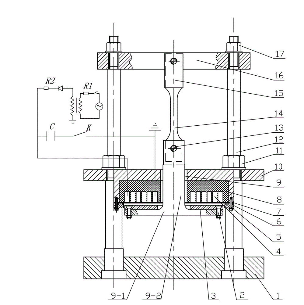
[0029] Specific implementation mode one: combine figure 1 and figure 2 Description, a high-speed unidirectional tensile test device, the device includes a base plate 1, a driving piece 3, a coil 4, a rigid coil stop ring 6, an insulating partition 7, a tensile mold 9, a coil support sleeve 10, a test Sample fixing plate 16 and two pull rods 12;

[0030] The center of the coil support sleeve 10 is provided with a connected inner shoulder hole and a through hole from bottom to top, the coil 4 is fixed in the inner shoulder hole of the coil support sleeve 10, and the sample fixing plate 16 is arranged on the front of the coil support sleeve 10 Above, the bottom plate 1 is arranged directly below the coil support sleeve 10, and the two pull rods 12 are arranged symmetrically with respect to the vertical center line of the base 1. The sample fixed plate 16 is detachably connected, and the lower end of the coil support sleeve 10 is provided with a rigid coil limit ring 6, and an ...

specific Embodiment approach 2

[0031] Specific implementation mode two: combination figure 1 Explain that the coil 4 described in this embodiment is a flat coil, the wire of the coil 4 is a copper wire, the cross section of the copper wire is rectangular, there is a gap between two adjacent copper wires, and a high voltage is used between the copper wires and the copper wires. Insulation cladding separates. The undisclosed technical features in this embodiment are the same as those in the first embodiment.

specific Embodiment approach 3

[0032] Specific implementation mode three: combination figure 1 To illustrate, the driving piece 3 in this embodiment is a red copper plate with a thickness of 5-8 mm. The undisclosed technical features in this embodiment are the same as those in the first embodiment.


PUM

PropertyMeasurementUnit
thicknessaaaaaaaaaa

Abstract

The invention discloses a high-speed one-way tensile test device and method, relates to a one-way tensile test device and method and aims to solve the problems of expensive test equipment and difficulty in obtaining a stress-strain relation curve in research on the constitutive relation of a metal material under the condition of high-speed elongation strain by using a hopkinson bar test. A coil is fixed in a coil supporting sleeve; two pull rods are connected with a bottom plate; the pull rods are detachably connected with the coil supporting sleeve and a sample fixing plate; a rigid coil limiting ring, an insulating partition plate and the coil supporting sleeve are detachably connected; and a drawing die comprises a base and a drawing rod, wherein the drawing rod is fixedly connected with the base, the drawing rod sequentially penetrates out of the coil limiting ring, the insulating partition plate, the coil framework and the coil supporting sleeve, a driving plate is arranged between the base and the rigid coil limiting ring and detachably connected with the base, and leading wires at two ends of the coil are connected with a capacitor bank which is controlled by a high-voltage switch to discharge. The high-speed one-way tensile test device and method are used for carrying out high-speed one-way tensile test on a standard tensile sample.

Description

technical field [0001] The invention relates to a unidirectional tensile test device and method. Background technique [0002] The stress-strain curve of a material is the most intuitive and commonly used method to measure the mechanical properties of a material. The mechanical properties of materials under normal stress or plastic deformation are usually measured by quasi-static tensile stress-strain curves. However, with the development of modern industry and science and technology, the performance and evaluation of mechanical properties of metal materials, building materials, superconducting materials, and composite materials under instantaneous impact loads, impacts, and other working conditions are particularly important. Pay attention to. For example, the structural integrity performance of thin steel car panels under instantaneous impact conditions, the evaluation of the bearing capacity of building materials such as steel bars under externally reinforced impact con...

Claims


Application Information

Patent Timeline
Patent Type & Authority Applications(China)
IPC IPC(8): G01N3/08G01N3/02
Inventor 于海平苏海韩玉杰徐俊瑞李春峰
Owner HARBIN INST OF TECH
Why Eureka
Try Eureka