
Positive and negative voltage generating circuit

A negative pressure generating circuit and a technology for generating circuits, applied in electrical components, adjusting electrical variables, instruments, etc., can solve the problems of waste of electricity, increase product cost, easy to generate interference, etc., and achieve the effect of reducing product cost and reducing interference.

Inactive Publication Date: 2013-02-27
SHENZHEN XINGUODU TECH
View PDF3 Cites 9 Cited by
  • Summary
  • Abstract
  • Description
  • Claims
  • Application Information

AI Technical Summary

Problems solved by technology

[0003] The output current of the above two circuits can generally reach hundreds of milliamperes or even several amperes. When these two circuits are used to provide positive and negative bias voltage for LCD or negative voltage for 232 communication circuit, since the equipment is in standby state Only a few microamperes of current are needed, so it will cause a waste of electricity, and it is not suitable for occasions with small current requirements. In addition, DC-DC booster circuits and DC-DC reverse polarity circuits must use DC-DC Chips, inductors and large capacitors, these components will increase the cost of the product and occupy a large space, which is not conducive to the miniaturization of the product. At the same time, because these two circuits have a high switching frequency, they will generate large electromagnetic interference. In practical applications, more protection measures need to be added to prevent interference from interference sources to other circuit modules
[0004] Therefore, the existing booster circuit and negative voltage circuit are not only not suitable for occasions with small current requirements, but also have high cost and are prone to interference

Method used


Image

  • Positive and negative voltage generating circuit

Examples


Embodiment Construction

[0016] The present invention will be described in more detail below in conjunction with the accompanying drawings and embodiments.

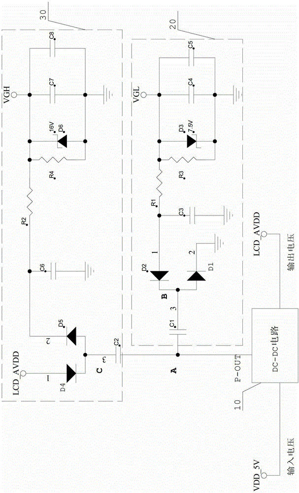
[0017] The present invention discloses a positive and negative voltage generation circuit, which includes: a DC-DC circuit 10, which is used to convert the input voltage from DC to DC, output a DC voltage through the voltage output terminal LCD_AVDD, and output a DC voltage through the pulse output terminal P -OUT outputs a square wave signal; a negative voltage generating circuit 20, which is connected to the pulse output terminal P-OUT of the DC-DC circuit 10, is used to convert the square wave signal output by the DC-DC circuit 10 into Negative voltage; a positive voltage generating circuit 30, which is connected to the pulse output terminal P-OUT of the DC-DC circuit 10, and is used for boosting the square wave signal output by the DC-DC circuit 10 through capacitor bootstrap. In the above circuit structure, the DC-DC circuit 10 may be any on...


PUM


Abstract

The invention discloses a positive and negative voltage generating circuit, which comprises a DC-DC (direct current to direct current) circuit used for performing DC-DC conversion of input voltage and then outputting direct-current voltage through a voltage output end and outputting square signals through a pulse output end; a negative voltage generating circuit connected with the pulse output end of the DC-DC circuit and used for converting the square signals output from the DC-DC circuit into negative voltage by bootstrap of a capacitor; and a positive voltage generating circuit connected with the pulse output end of the DC-DC circuit and used for performing boost conversion of the square signals output from the DC-DC circuit by the bootstrap of the capacitor. The positive and negative voltage generating circuit disclosed by the invention is applicable to supplying the positive and negative voltage to a circuit with a small demand on current and capable of reducing the product cost and reducing the interference at the same time.

Description

technical field [0001] The invention relates to a voltage conversion circuit, in particular to a positive and negative voltage generation circuit. Background technique [0002] In the process of developing electronic products, it is necessary to consider the influence of power supply on electronic products. If the design of the power supply circuit is not good, the whole system may not work properly. In existing electronic products, there is usually only one input voltage, but the voltage required by each module in the circuit is different, which leads to several voltages in the entire circuit at the same time, and sometimes a negative voltage is required. It is necessary to step up, step down, and reverse the polarity of the input voltage to make it meet the voltage required by each module of the circuit. The more common boosting method is to use a DC-DC boosting circuit. The DC-DC boosting circuit is characterized by high conversion efficiency and large output current; th...

Claims


Application Information

Patent Timeline
Patent Type & Authority Applications(China)
IPC IPC(8): H02M3/00H02M3/06H02M3/08
Inventor 黄善兵翟建光甘彦君
Owner SHENZHEN XINGUODU TECH
Learn More