Power supply control circuit and vehicle-mounted air conditioner
A technology of power supply control circuit and power supply voltage, which is applied in battery circuit devices, control/regulation systems, electric vehicles, etc., and can solve unfavorable production and use, high requirements for anti-pressure of inverter circuits, compressor cost and large volume of compressors, etc. problems, to avoid additional costs, save the effect of voltage suppression circuit
- Summary
- Abstract
- Description
- Claims
- Application Information
AI Technical Summary
Problems solved by technology
Method used
Image
Examples
Embodiment 1
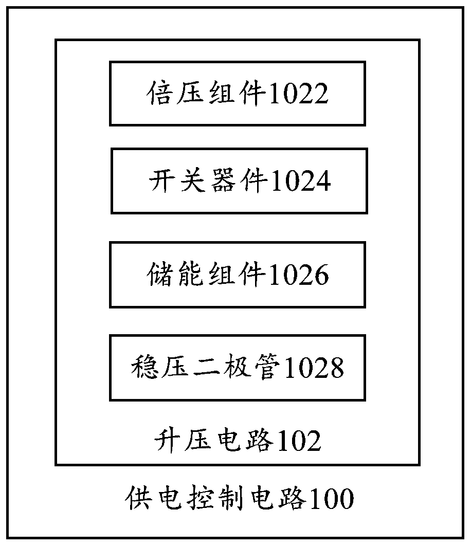
[0040] Such as figure 1 As shown, according to the embodiment of the first aspect of the present invention, a power supply control circuit 100 is proposed, which includes: a booster circuit 102 for performing voltage conversion on the power supply voltage to be input to the load.
[0041] Specifically, the boost circuit 102 includes a voltage doubling component 1022 configured to store or release the supply voltage provided by the input terminal of the boost circuit 102, wherein the voltage doubling component 1022 is provided with at least two groups, at least two groups of voltage doubling Components 1022 are interconnected.
[0042] The power supply control circuit 100 provided in this embodiment considers that the battery of the car is charged by the generator of the car. When the battery is suddenly disconnected from the generator during the operation of the generator, the generator as an inductive device will In the case of a drop, voltage compensation will be caused to ...
Embodiment 2
[0044] Such as figure 1 As shown, according to an embodiment of the present invention, in addition to the features defined in the above embodiments, further: the boost circuit 102 further includes a switching device 1024 and an energy storage component 1026 .
[0045] Specifically, the switching device 1024 is connected to the voltage doubler component 1022 and is configured to control the voltage doubler component 1022 to be turned on or off, one end of the energy storage component 1026 is connected to the voltage doubler component 1022, and the other end of the energy storage component 1026 is connected to the boost circuit The output terminal of 102 is connected, and the energy storage component 1026 is configured to boost the power supply voltage released by the voltage multiplier component 1022 and transmit it to the output terminal of the boost circuit 102 .
[0046] In this embodiment, the switching device 1024 is connected to the voltage doubling component 1022, and is...
Embodiment 3
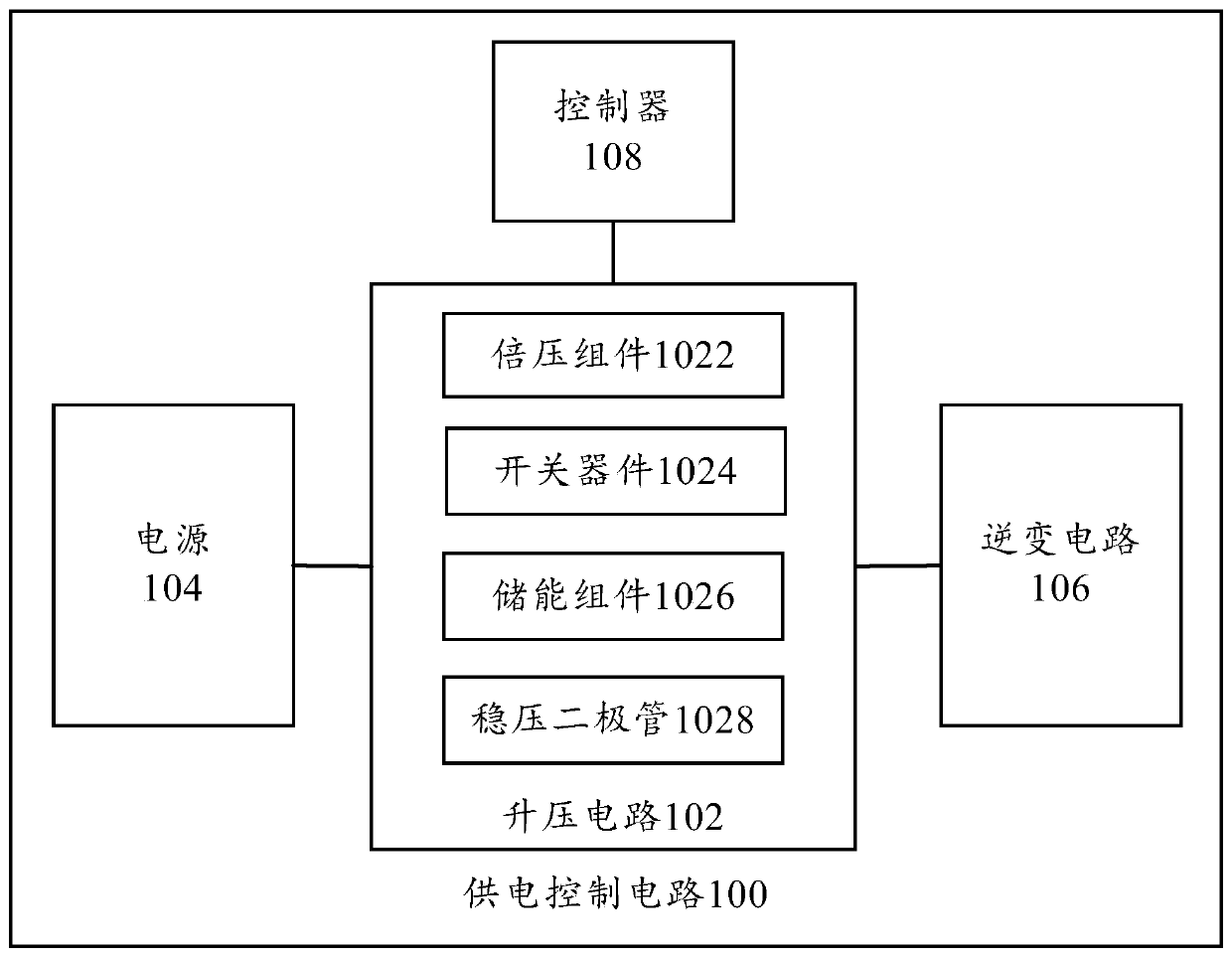
[0048] Such as figure 1 and figure 2 As shown, according to an embodiment of the present invention, a power supply control circuit 100 is proposed, which includes: a boost circuit 102 , a power supply 104 , an inverter circuit 106 and a controller 108 .
[0049] Specifically, the power supply 104, the inverter circuit 106, and the controller 108 are connected to the boost circuit 102, the power supply 104 is configured to provide a supply voltage, and the inverter circuit 106 is configured to control the power supply signal to supply power to the load according to the converted voltage, and the control The converter 108 is configured to output a control instruction, and control the booster circuit 102 to work according to a preset switching frequency and duty cycle.
[0050] In this embodiment, the power supply 104 is used to provide electric energy for the load. Specifically, the power supply voltage of the power supply 104 is boosted by the booster circuit 102 to obtain a ...
PUM
 Abstract
Description
Claims
Application Information
 - R&D
- Intellectual Property
- Life Sciences
- Materials
- Tech Scout
- Unparalleled Data Quality
- Higher Quality Content
- 60% Fewer Hallucinations
Browse by: Latest US Patents, China's latest patents, Technical Efficacy Thesaurus, Application Domain, Technology Topic, Popular Technical Reports.
© 2025 PatSnap. All rights reserved.Legal|Privacy policy|Modern Slavery Act Transparency Statement|Sitemap|About US| Contact US: help@patsnap.com


