internal combustion engine

A technology of internal combustion engine and crankshaft, which is applied in mechanical equipment, engine control, machine/engine, etc., can solve the problem that internal combustion engine cannot be used, and achieve the effect of avoiding transmission distortion.

Inactive Publication Date: 2016-08-24
SCHAEFFLER TECH AG & CO KG
View PDF6 Cites 0 Cited by
  • Summary
  • Abstract
  • Description
  • Claims
  • Application Information

AI Technical Summary

Problems solved by technology

This kinematic principle cannot be applied to internal combustion engines with crankshaft components arranged parallel to each other

Method used


Image

  • internal combustion engine

Examples


Embodiment Construction

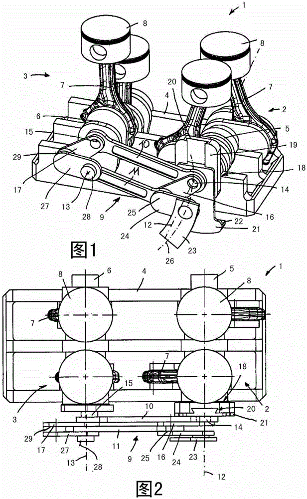
[0020] figure 1 and 2 A schematic diagram of an internal combustion engine 1 with two subunits 2 , 3 is shown from different perspectives. The subunits 2 , 3 are accommodated in a common housing 4 and have cranked crankshaft parts 5 , 6 arranged parallel to each other, on which in each case two pistons 8 are arranged by means of connecting rods 7 . to form a four-cylinder piston engine.

[0021] The two crankshaft parts 5 , 6 are forcibly coupled by means of a coupling device 9 . For this purpose, the coupling device 9 has two connecting rods 10 , 11 , wherein the connecting rod 10 is arranged so as to be twistable directly on crank pins 14 , 15 respectively arranged on the crankshaft parts 5 , 6 . The second connecting rod 11 is hingedly connected to the crank pins 14 , 15 by means of hinge levers 16 , 17 . The length of the articulated levers 16 , 17 causes the connecting rods 10 , 11 to be offset in the circumferential direction with respect to the axes of rotation 12 , 1...


PUM


Abstract

The invention relates to an internal combustion engine composed of a plurality of sub-units with crankshaft parts arranged in each case parallel to one another, on which crankshaft parts in each case at least one piston is held by means of a connecting rod on a crank of the crankshaft part, wherein a first sub-unit is operated permanently during the operation of the internal combustion engine and at least one second sub-unit can be deactivated. To be able to couple the crankshaft parts of the sub-units to one another without play and realize decoupling without the use of couplings arranged between the crankshaft parts, the crankshaft parts are positively coupled to one another by means of a first connecting rod and a second connecting rod which, by means of coupling levers, is arranged offset with respect to the first connecting rod about the axes of rotation of said connecting rods by a predefined angle, which connecting rods are rotatably held on in each case one crank pin of the crankshaft parts, and the sub-units are provided such that they can be decoupled from one another in terms of rotation by the displacement of one crank pin coaxially with respect to an axis of rotation of the crankshaft part assigned to said crank pin.

Description

technical field [0001] The invention relates to an internal combustion engine comprising a plurality of subunits each having crankshaft parts arranged parallel to one another, on which in each case at least one piston is received by means of a connecting rod on a crank of the crankshaft part , wherein the first subunit is permanently operated during operation of the internal combustion engine and at least one second subunit can be switched off. Background technique [0002] The internal combustion engine converts chemical energy into kinetic energy by burning the energy stored in the fuel in such a way that, in a piston-type internal combustion engine, the piston, which is received on the crankshaft by means of connecting rods, will be in the cylinder in the case of rotation of the crankshaft according to the two-stroke or four-stroke principle. Perform ascent and descent movements. Especially in motor vehicles, internal combustion engines have a wide power range in order t...

Claims


Application Information

Patent Timeline
Patent Type & Authority Patents(China)
IPC IPC(8): F16H21/12F02D17/02F02D25/04
CPCF02B75/228F02D17/02
Inventor O·弗里德曼
Owner SCHAEFFLER TECH AG & CO KG
Why Eureka
Try Eureka