Check patentability & draft patents in minutes with Patsnap Eureka AI!

Fluidized bed furnace and waste processing method

A fluidized bed furnace, waste technology, applied in fluidized bed combustion equipment, incinerators, combustion methods, etc., can solve problems such as inability to obtain stable energy

Inactive Publication Date: 2013-02-27
KOBELCO ECO-SOLUTIONS CO LTD
View PDF7 Cites 0 Cited by
  • Summary
  • Abstract
  • Description
  • Claims
  • Application Information

AI Technical Summary

Problems solved by technology

[0006] For example, when generating electricity using combustible gas generated in a gas engine, stable energy cannot be obtained if the combustible gas fluctuates greatly

Method used


Image

  • Fluidized bed furnace and waste processing method
  • Fluidized bed furnace and waste processing method
  • Fluidized bed furnace and waste processing method

Examples


Embodiment Construction

[0021] Hereinafter, an embodiment of the present invention will be described with reference to the drawings.

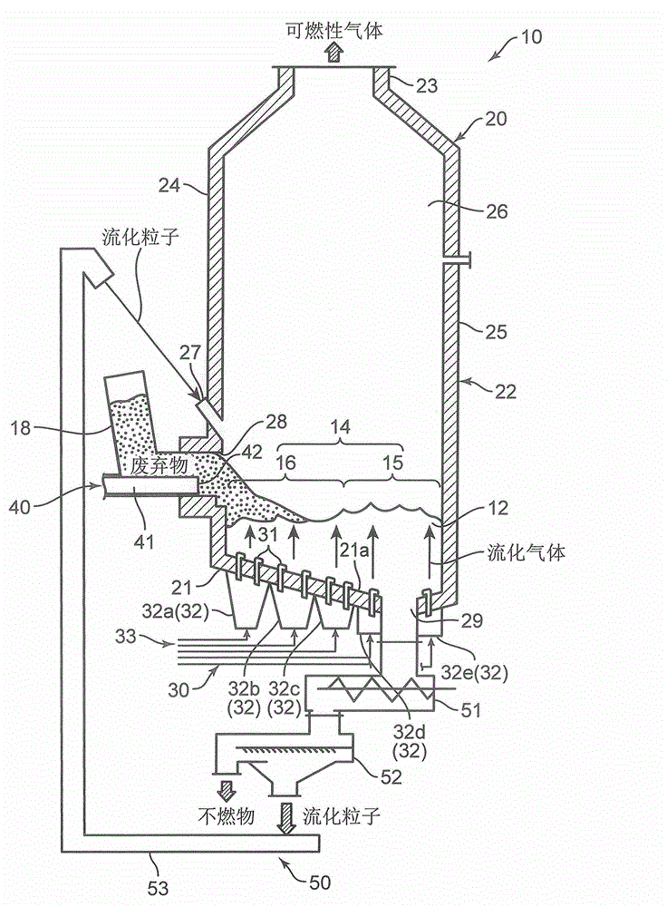
[0022] The fluidized bed furnace according to this embodiment heats waste with high-temperature fluidized particles, thereby extracting combustible gas from the waste. Such as figure 1 As shown, this fluidized bed furnace includes fluidized particles 12 , a furnace main body 20 , a gas supply unit 30 , a waste supply unit 40 , and a sand circulation device 50 .

[0023] The fluidized particles 12 are used to form a fluidized bed 14 inside the furnace main body 20 and to heat waste 18 . That is, the fluidized particles 12 heated to a high temperature by the combustion of a part of the waste 18 are mixed with the waste 18, and the waste 18 is gasified to generate a combustible gas. The fluidized particles 12 of the present embodiment are, for example, silica sand or the like.

[0024] The furnace main body 20 has fluidized particles 12 inside, and combustible gas is...


PUM


Abstract

The invention discloses a fluidized bed furnace and a waste processing method. The disclosed fluidized bed furnace is characterized by: forming a first fluid region (15) by blowing fluidizing gas towards fluid particles from the periphery of a non-combustibles discharge port (29); forming a second fluid region (16) of which the degree of fluidization of fluid particles (12) is low by blowing fluidizing gas between the first fluid region (15) and a front wall (24) at a lower flow speed than that at the first fluid region (15); returning fluid particles (12) discharged from the non-combustibles discharge port (29) from the front wall (24) side to the fluidized bed (14), forming a flow of fluid particles (12) in the fluidized bed from the front wall (24) side towards the non-combustibles discharge port (29); supplying waste (18) from the front wall (24) to the top of the fluidized bed (14), retaining waste (18) on the second fluid region (16); and advancing the retained waste (18) progressively into the first fluid region (15), gasifying the waste (18).

Description

technical field [0001] The present invention relates to a fluidized bed furnace and a waste treatment method for extracting combustible gas from waste by heating the waste in a fluidized bed that fluidizes fluidizable particles. Background technique [0002] Conventionally, a fluidized bed furnace disclosed in Patent Document 1 is known as a fluidized bed furnace. Such as Figure 11 As shown, the fluidized bed furnace has: a furnace body 104 having fluidized sand (fluidized particles) 102 at the furnace bottom; and air is supplied to the fluidized sand 102 at the furnace bottom to fluidize the fluidized sand 102 to form Air supply 106 for the fluidized bed. The furnace body 104 has side walls. The side wall is provided with an input portion 108 for inputting waste into the fluidized bed. [0003] In this fluidized bed furnace 100 , an air supply unit 106 supplies air to the high-temperature fluidized sand 102 . As a result, the fluidized sand 102 becomes fluidized in a f...

Claims


Application Information

Patent Timeline
Patent Type & Authority Applications(China)
IPC IPC(8): F23G5/027F23C10/02F23G5/30
CPCF23G5/027F23G5/30F23C10/20F23C10/22F23C10/26F23G2205/101
Inventor 河合卓也细田博之伊藤正
Owner KOBELCO ECO-SOLUTIONS CO LTD
Features
  • R&D
  • Intellectual Property
  • Life Sciences
  • Materials
  • Tech Scout
  • Unparalleled Data Quality
  • Higher Quality Content
  • 60% Fewer Hallucinations
Learn More