Battery connection member and battery connection body

A battery connection and component technology, which is applied in the field of battery connection parts and battery connectors, can solve the problems of increased mold costs and achieve the effect of reducing mold costs and material costs

Active Publication Date: 2013-02-27
YAZAKI CORP
View PDF4 Cites 10 Cited by
  • Summary
  • Abstract
  • Description
  • Claims
  • Application Information

AI Technical Summary

Problems solved by technology

In addition, if the size of the wiring groove 123 cannot be reduced, the battery connection plate 100 will also be increased in size, resulting in a problem of increased material costs and mold costs.

Method used


Image

  • Battery connection member and battery connection body
  • Battery connection member and battery connection body
  • Battery connection member and battery connection body

Examples


Embodiment Construction

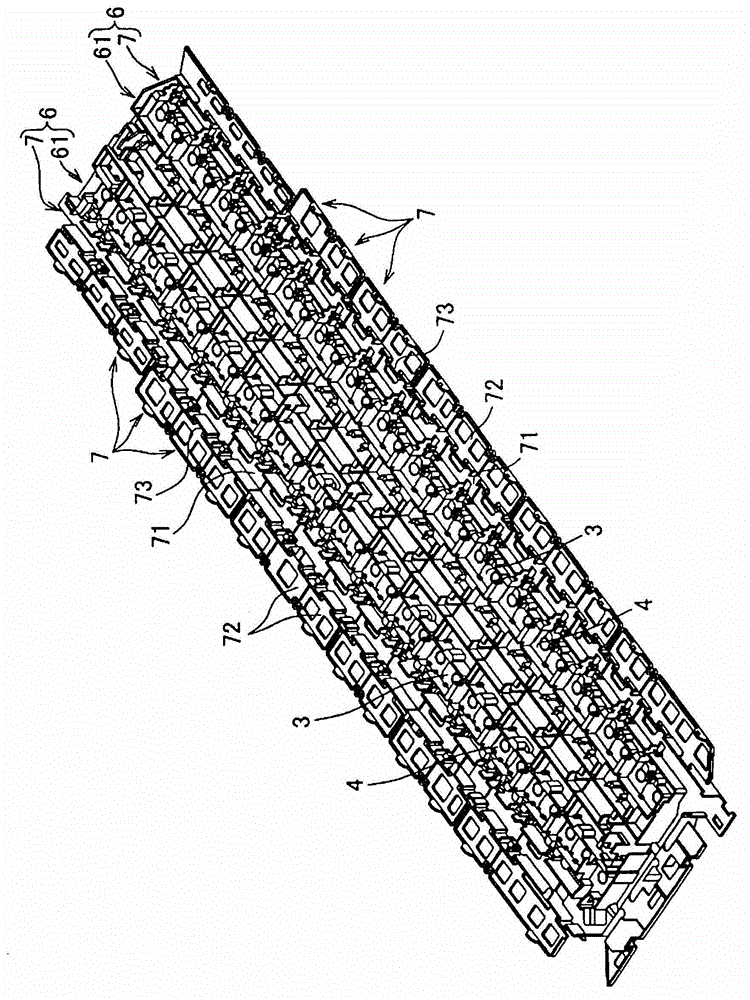
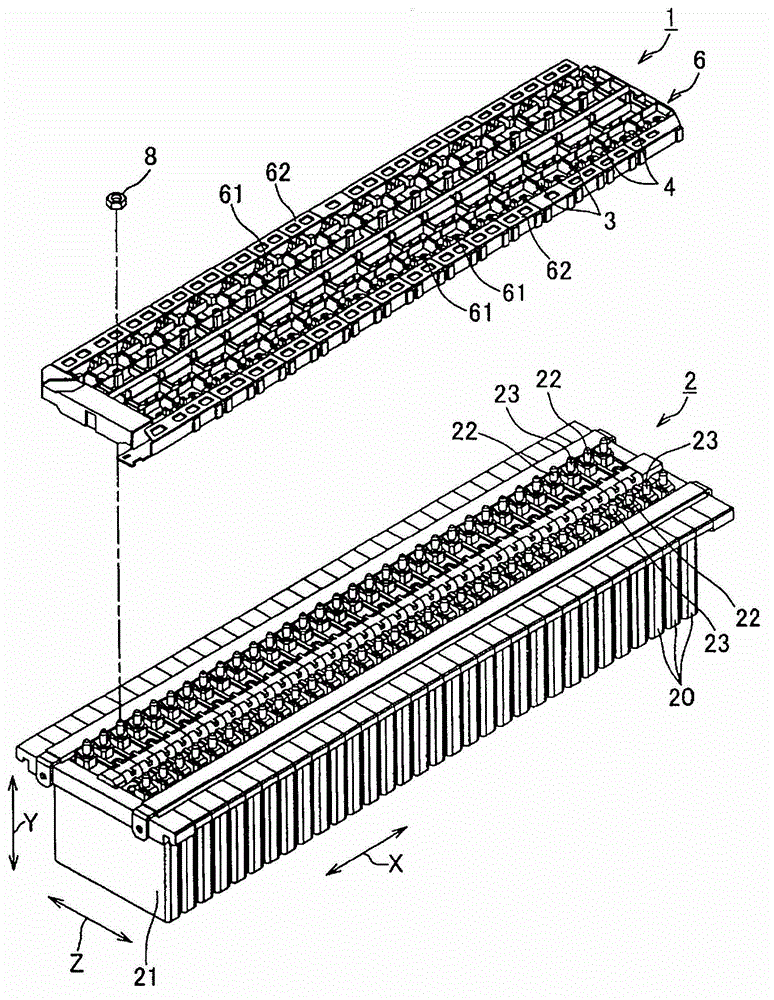
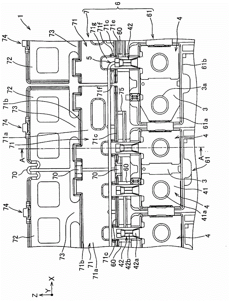
[0026] Below, refer to Figure 1 to Figure 5 The accompanying drawings illustrate one embodiment of the battery connecting member and the battery connecting body according to the present invention.

[0027] Such as figure 1 , 2 As shown, the battery connector 1 of the present invention is mounted on a battery assembly 2 to constitute a power supply device. In addition, the power supply unit is mounted on an electric vehicle that runs using an electric motor, a hybrid vehicle that runs on an engine and an electric motor, and the like, and is a component that supplies electric power to the electric motor. In addition, the battery assembly is formed by alternately stacking batteries (prismatic batteries) having a positive electrode at one end and a negative electrode at the other end.

[0028] First, the battery assembly 2 such as figure 2 As shown, there are a plurality of batteries 20 and a fixing member (not shown) that overlaps and fixes the plurality of batteries 20 . ...


PUM


Abstract

Disclosed are a battery connection member and a battery connection body that prevent interference between a battery and terminal arranged inside an arrangement part, and make the arrangement part smaller. A battery connection member (6) comprises: a plurality of housing parts (61), which houses bus bars (3) that connect a plurality of batteries in a series, and one or a plurality of terminals (4) that are electrically connected to the bus bars (3); and arrangement parts (71), which are arranged side by side along the plurality of housing parts (61) in a direction that intersects with the direction in which a wire (5) is connected to a terminal (4), and within which the wire (5) curves in the vicinity of the crimp portion of the terminal (4). Each arrangement part (71) comprises: a communication section (71e), which is formed in communication with the inside of the arrangement part (71), and at which the terminal section of the crimp portion of the terminal (4) is positioned; and a wire protection section (71f), which is a continuation of the communication section (71e) and protrudes toward the inside of the arrangement part (71), and which is formed in such a manner as to prevent the terminal (4) positioned at the communication section (71e) and the wire (5) connected to another terminal (4) from coming into contact.

Description

technical field [0001] The present invention relates to a battery connection member having a plurality of bus bars for accommodating a plurality of batteries connected in series and one or more terminals electrically connected to the bus bars, and a battery connection body having the battery connection member. a plurality of receiving parts are arranged in parallel along a direction intersecting with the connection direction of the electric wires with respect to the terminals, and a wiring part of the electric wires bent near the crimping parts of the terminals is routed inside. Background technique [0002] For example, in an electric vehicle traveling using an electric motor, a hybrid vehicle traveling using an engine and an electric motor in combination, the power supply device described above is mounted as a driving source of the electric motor. In this power supply unit, the battery connection plate disclosed in Patent Document 1 is used. [0003] Image 6 In the above...

Claims


Application Information

Patent Timeline
Patent Type & Authority Applications(China)
IPC IPC(8): H01M2/10H01M2/20H01M50/209H01M50/507H01M50/51H01M50/55H01M50/553
CPCY02E60/12H01M2/206H01M2/20H01M2/1061H01M2/1077H01M2220/20Y02E60/10H01M50/507H01M50/51H01M50/55H01M50/553
Inventor 小笠原茂之佐藤胜则山下清贵
Owner YAZAKI CORP
Why Eureka
Try Eureka