

Signal processing system
A signal processing and signal technology, applied in transmission systems, digital transmission systems, security communication devices, etc., can solve problems such as loss of sales and reduced brand image
- Summary
- Abstract
- Description
- Claims
- Application Information
AI Technical Summary
Problems solved by technology
Method used
Image

Examples
Embodiment approach 1
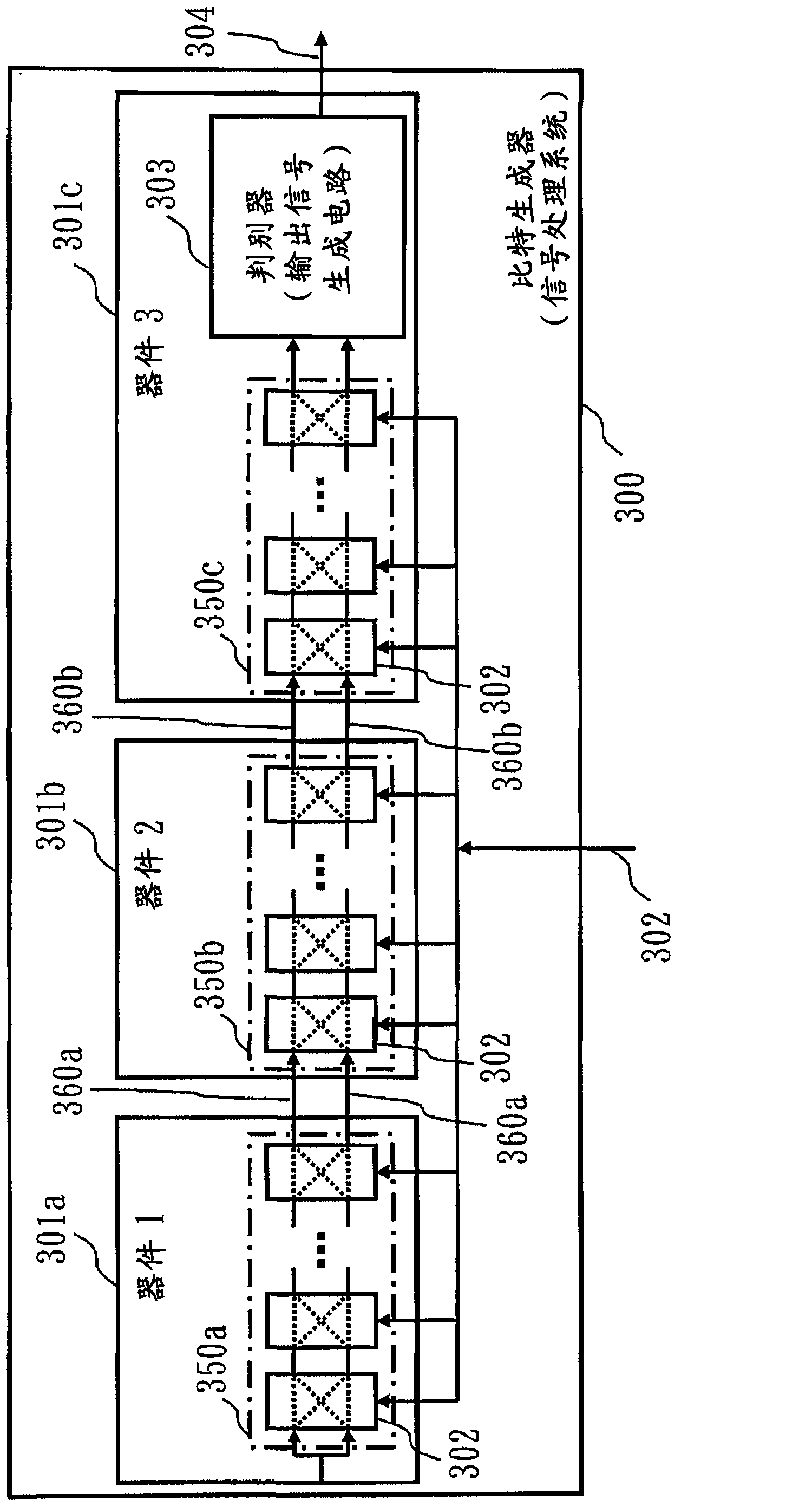
[0082] figure 1 A configuration example of the bit generator 300 (signal processing system) of this embodiment is shown.
[0083] exist figure 1 In the shown bit generator 300 , the circuit of Non-Patent Document 1 is divided and mounted on three semiconductor devices (also simply referred to as devices).
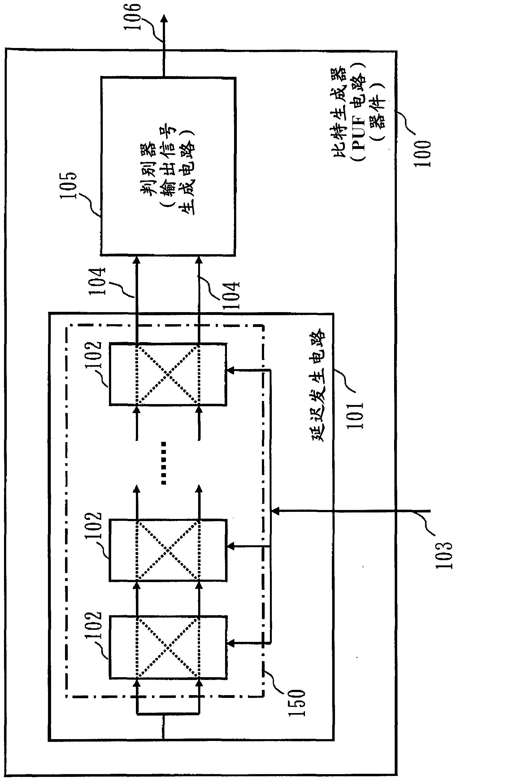
[0084] In Non-Patent Document 1, a delay generating circuit composed of two channels corresponds to a characteristic circuit.
[0085] exist figure 1 in, make Figure 7 The interleaver 102 in the delay generating circuit 101 is distributed to three semiconductor devices 301a, 301b, 301c, and the delay of two channels is determined by all the characteristics of the three semiconductor devices 301a, 301b, 301c.
[0086] The discriminator 303 determines before and after the arrival of the signals passing through the two channels, and converts the determination result into bits and outputs it as an output signal 304 .
[0087] The discriminator 303 is an example of an ou...
Embodiment approach 2
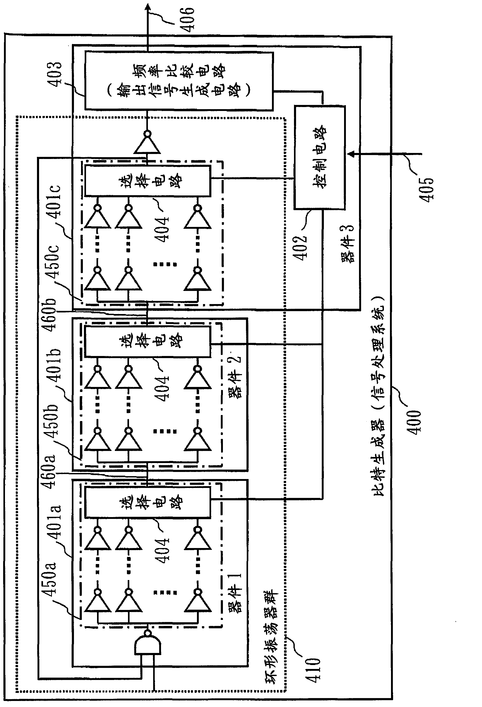
[0119] image 3 A configuration example of the bit generator 400 (signal processing system) of this embodiment is shown.
[0120] exist image 3 In the shown bit generator 400, the circuit of Patent Document 1 is divided and mounted on three semiconductor devices.
[0121] In Patent Document 1, a ring oscillator corresponds to a characteristic circuit.
[0122] exist image 3 in, by adding Figure 8 The N ring oscillators in the circuit are divided into three partial circuits and arranged in three semiconductor devices, thus constituting the bit generator 400 whose bits are determined by all the characteristics of the three semiconductor devices.
[0123] exist image 3 Among them, the bit generator 400 includes a ring oscillator group 410 , a control circuit 402 , and a frequency comparison circuit 403 .
[0124] The ring oscillator group 410 is composed of N (N≧2) ring oscillators that are divided and arranged in three semiconductor devices. At the boundary between de...
Embodiment approach 3
[0161] Figure 5 A configuration example of the bit generator 500 (signal processing system) of this embodiment is shown.
[0162] exist Figure 5 In the shown bit generator 500 , the circuit of Non-Patent Document 1 is divided and mounted on three semiconductor devices, and the wiring of the substrate on which the devices are mounted is further included as a characteristic circuit of the PUF.
[0163] compared to figure 1 ,exist Figure 5 , the range 507 indicated by the dotted line is different.
[0164] in addition, Figure 5 Only the main part is shown, the structure outside the range 507 shown by the dotted line is with figure 1 same.
[0165] In the range 507 , the connection paths 501 and 502 between devices include a plurality of branch paths 503 and 504 , and the branch paths 503 and 504 are accommodated in the next sequential device 2 ( 511 b ).
[0166] The branch paths 503 a , 503 b , 504 a , and 504 b are constituted by wiring of a substrate on which each...
PUM
 Abstract
Description
Claims
Application Information