Sensor output IC and sensor device

一种传感器、输出端子的技术,应用在传感器用输出IC以及传感器装置领域,能够解决制造成本增大、价格昂贵、传感器装置110电路规模以及制造成本增大等问题,达到抑制制造成本、抑制电路规模的效果

Active Publication Date: 2011-09-21
OMRON CORP
View PDF8 Cites 6 Cited by
  • Summary
  • Abstract
  • Description
  • Claims
  • Application Information

AI Technical Summary

Problems solved by technology

[0009] However, in the case of using the above-mentioned timer circuit, since it is necessary to provide circuit elements having capacitance, resistance, etc. outside the sensor output IC 121, the circuit scale and manufacturing cost of the sensor device 110 will increase.
In addition, in the case of using the above-mentioned logic circuit, it is necessary to install the above-mentioned logic circuit inside the output IC 121 for the sensor, so the manufacturing process of the output IC 121 for the sensor is limited to expensive, and the manufacturing cost increases.
In this way, the conventional short-circuit protection circuit has problems in achieving further miniaturization and cost reduction of the sensor device 110

Method used


Image

  • Sensor output IC and sensor device
  • Sensor output IC and sensor device
  • Sensor output IC and sensor device

Examples


Embodiment 1

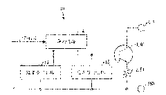
[0056] Figure 4 express figure 1 An example of the circuit of the sensor output IC10 shown. First, a circuit example of the drive circuit 14 in the sensor output IC 10 will be described. As shown in the figure, the driving circuit 14 is configured to include a constant current source CC11, NPN transistors Q11 and Q12, and a resistor R11.

[0057] The collector terminal of the transistor Q11 is connected to the power supply line Vcc, the detection signal from the sensor 120 is input to the base terminal, and the emitter terminal is connected to the base terminal of the output transistor 11 via the resistor R11. In addition, the collector terminal of the transistor Q12 is connected to the constant current source CC11 and the base terminal of the transistor Q11, the base terminal is connected to the emitter terminal of the transistor Q11, and the emitter terminal is connected to the base terminal of the output transistor 11.

[0058] Therefore, when the current from the cons...


PUM


Abstract

The invention relates to a sensor output IC and a sensor device. A load-short-circuit protection function is realized while a circuit scale and production cost of a sensor device are reduced than ever before. A sensor output IC (10) includes an output transistor (11) that turns on and off between output terminals based on a detection signal from a sensor (120). The sensor output IC (10) includes a temperature-limiting circuit (13) and a voltage-limiting circuit (15). When a temperature at the sensor output IC (10) becomes a predetermined value or more, the temperature-limiting circuit (13) maintains the output transistor (11) in an off state, and the voltage-limiting circuit (15) limits a base potential (V B ) at the output transistor (11) to a predetermined value or less.

Description

technical field [0001] The present invention relates to a sensor output IC and a sensor device including a switching element for turning ON / OFF between output terminals based on a detection signal from a sensor. Background technique [0002] Figure 6 A schematic configuration of a general sensor system that performs various operations based on detection signals from sensors is shown. As shown in the figure, the sensor system 100 has a structure in which a power source 111 and a load 112 are connected to a sensor device 110 . The power supply 111 is connected to power supply terminals 113 , 113 of the sensor device 110 to supply power to the sensor device 110 . Furthermore, load 112 performs various operations based on detection signals from sensor 120 (described later) by supplying electric power, and output terminals 114 , 114 are connected to power supply 111 and load 112 connected in series. [0003] In addition, in the illustrated example, the - side of the power supp...

Claims


Application Information

Patent Timeline
Patent Type & Authority Applications(China)
IPC IPC(8): H03K17/08H03K17/722
CPCH03K17/08126H03K17/08112
Inventor 小西康允
Owner OMRON CORP
Why Eureka
Try Eureka