Oil-gas separator provided with conical spiral channel

A technology of oil and gas separator and spiral channel, which is applied in the direction of mechanical equipment, crankcase ventilation, machine/engine, etc. It can solve the problems of poor separation rate of oil mist, oil and gas, need to regularly update filter elements, complex structure, etc.

Active Publication Date: 2016-10-12
蔡婕
View PDF7 Cites 5 Cited by
  • Summary
  • Abstract
  • Description
  • Claims
  • Application Information

AI Technical Summary

Problems solved by technology

[0002] The oil and gas separators in the prior art are called filter element type with filter element structure, cyclone type with conical hollow structure, and centrifugal type with rotating blade structure. Among them, the filter element type oil and gas separator operates The method is pass-through, and the filter element needs to be updated regularly during operation, which is cumbersome and costly to operate and maintain; the cyclone oil-gas separator, which operates in the pass-through type, separates tiny mist-like oil droplets with a diameter of about 1 micron suspended in the gas during operation The effect is poor; the centrifugal oil-gas separator, the operation mode is active, the structure is complex, the rotation and connection links are many, the failure rate is high, and the manufacturing and maintenance costs are high; therefore, the existing technology has complex structure, troublesome maintenance, high failure rate, Problems and shortcomings of high cost and poor oil-gas separation rate of oil mist

Method used


Image

  • Oil-gas separator provided with conical spiral channel
  • Oil-gas separator provided with conical spiral channel
  • Oil-gas separator provided with conical spiral channel

Examples


Embodiment Construction

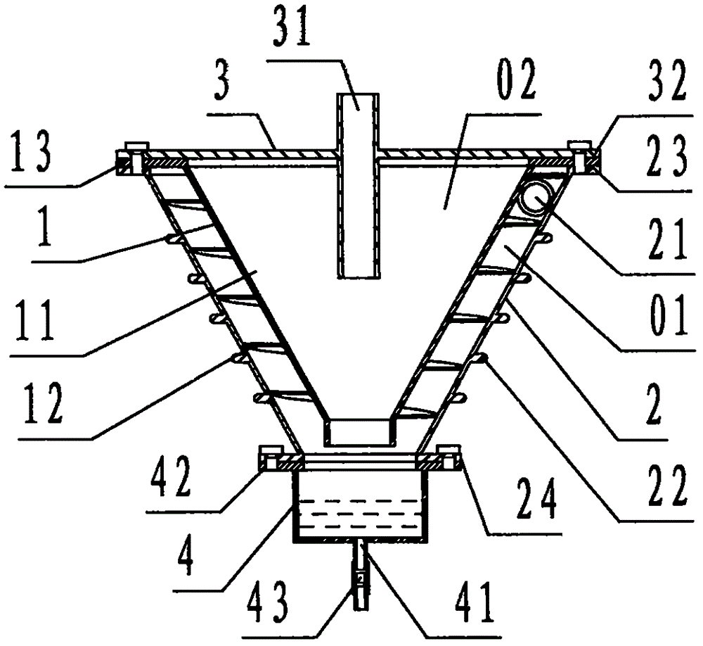
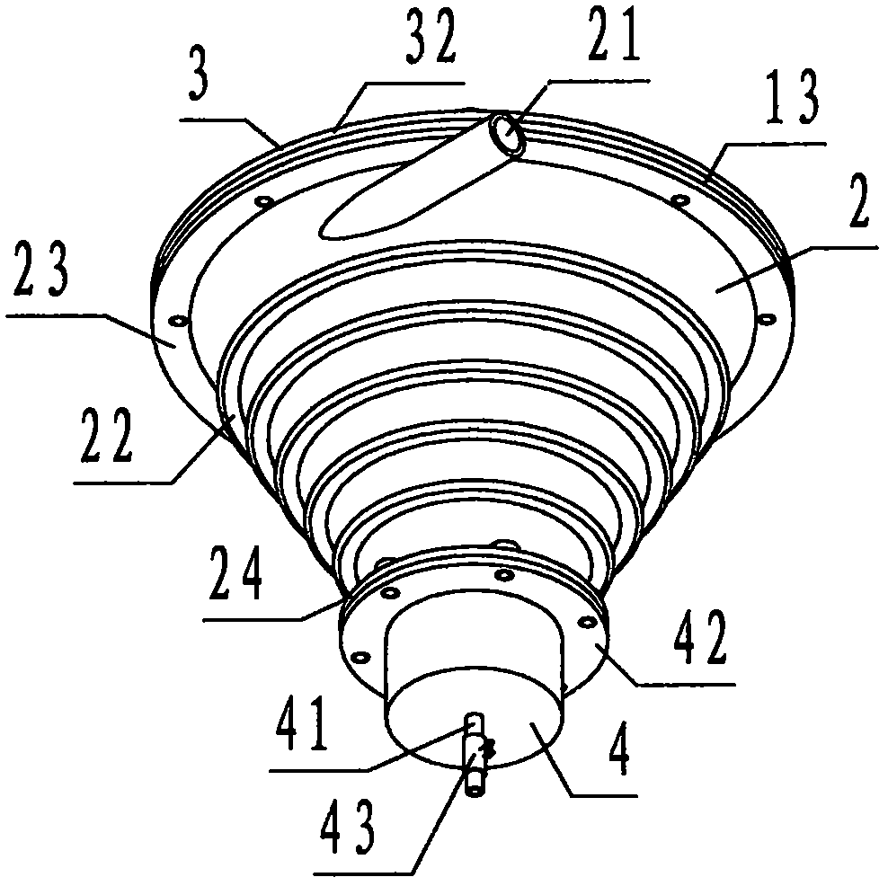
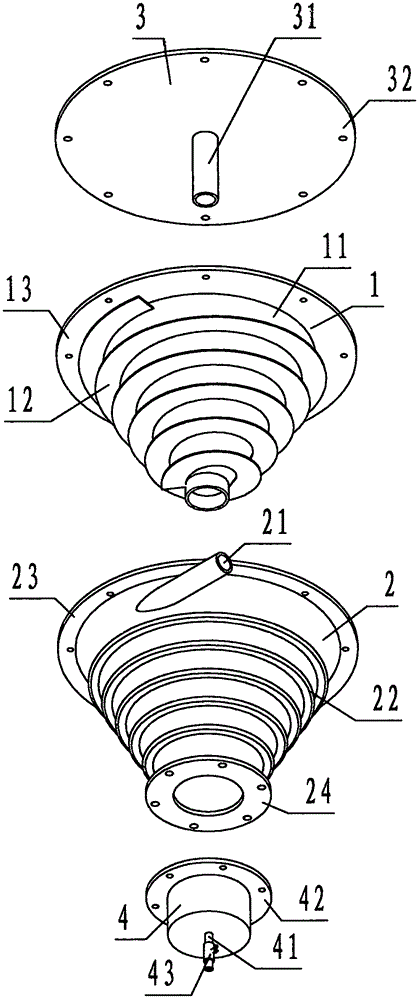
[0025] refer to Figure 1 ~ Figure 4 , a kind of oil-gas separator that is provided with conical spiral channel of the present invention, comprises conical spiral core 1, conical shell 2, upper cover 3, oil collecting bucket 4, wherein: described conical spiral core 1 is made of conical barrel 11, conical The spiral rib 12 and the core flange 13 are formed. The conical cylinder 11 is a hollow and thin-walled aluminum alloy member with a large top and a small bottom, open up and down, and a conical cylindrical shape. The upper edge of the conical cylinder 11 is provided with a horizontal ring. The flange is called the core flange 13, and the core flange 13 is evenly provided with a number of circular through holes for connection called upper connection holes; Convex rib is called conical spiral rib 12, and the pitch of described conical spiral rib 12 is equidistant;

[0026] The conical shell 2 is a hollow and thin-walled aluminum alloy member with a large top and a small bott...


PUM


Abstract

The invention discloses an oil-gas separator provided with a conical spiral channel. The oil-gas separator comprises a conical spiral core (1), a conical outer shell (2), an upper cover (3) and an oil collection hopper (4). By adopting the device composed of the components, the upper cover is located on the conical spiral core, the oil collection hopper is located under the conical outer shell, the conical spiral core is sleeved with the conical outer shell, and the downward spiral channel defined by a conical barrel, conical spiral ribs and the conical outer shell is the conical spiral channel; a cavity defined by the oil collection hopper, the conical spiral core and the upper cover is an air chamber; an oil mist inlet communicates with the upper end of the conical spiral channel, the lower end of the conical spiral channel communicates with the oil collection hopper, and an exhaust port communicates with the air chamber. During working, according to the technical scheme that oil mist enters the conical spiral channel through the oil mist inlet and is separated into oil and gas under the action of centrifugal force, the purposes of structure simplifying, non-maintenance, non-failure, cost reduction and high oil-gas separation rate of the oil mist of the oil-gas separator are achieved.

Description

technical field [0001] The invention relates to an oil-gas separator, in particular to an oil-gas separator provided with a conical spiral channel for separating oil mist in a crankcase of a diesel engine into oil liquid and gas. Background technique [0002] The oil and gas separators in the prior art are called filter element type with filter element structure, cyclone type with conical hollow structure, and centrifugal type with rotating blade structure. Among them, the filter element type oil and gas separator operates The method is pass-through, and the filter element needs to be updated regularly during operation, which is cumbersome and costly to operate and maintain; the cyclone oil-gas separator, which operates in the pass-through type, separates tiny mist-like oil droplets with a diameter of about 1 micron suspended in the gas during operation The effect is poor; the centrifugal oil-gas separator, the operation mode is active, the structure is complex, the rotation...

Claims


Application Information

Patent Timeline
Patent Type & Authority Applications(China)
IPC IPC(8): F01M13/04
CPCF01M13/04F01M2013/0422
Inventor 蔡婕
Owner 蔡婕
Why Eureka
Try Eureka