Aging test device for AC charging pile

An AC charging pile and aging device technology, which is applied to measurement devices, circuit devices, battery circuit devices, etc., can solve problems such as failure to ensure normal machine handshake communication, waste of AC power, large size, etc., and achieves environmental protection effects and significant economic benefits. , Reduce the cost of electricity, no high frequency interference effect

Active Publication Date: 2016-07-06
HENAN KAIMENG TECH CO LTD
View PDF6 Cites 5 Cited by
  • Summary
  • Abstract
  • Description
  • Claims
  • Application Information

AI Technical Summary

Problems solved by technology

[0002] Existing AC charging piles, AC billing devices, etc. often need to be connected to loads such as bulb heating wires to consume electric energy when testing aging, and are used to measure the current flowing through the equipment. The equipment works at a high current for a long time for a period of time to test the functional performance of the equipment. It is a waste of AC power; if the car charger is used to add a battery, the battery will be more and more full, the current will become smaller and smaller, and it will be discharged when it is full, which will not achieve the purpose of aging for a long time at the set current. Connect the actual useful load to the billing device, but there is no suitable test aging equipment with adjustable current
It is the aging of conventional heating wires, which has disadvantages such as inconvenient adjustment of current setting, large volume, heat generation, and fire hazards.
In addition, before the AC charging pile ages, it is necessary to shake hands with the vehicle and communicate with the vehicle. The heating and luminous load does not meet these conditions. It is often necessary to burn the test program or manually close the internal contactor of the AC charging pile. This is very troublesome and cannot guarantee recovery. After leaving the factory, the handshake communication of the machine is normal, but there are hidden dangers

Method used


Image

  • Aging test device for AC charging pile
  • Aging test device for AC charging pile
  • Aging test device for AC charging pile

Examples


Embodiment 1

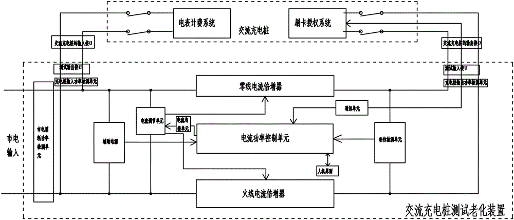
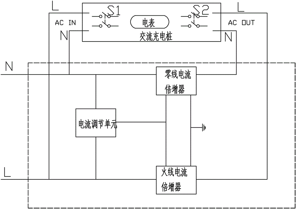
[0022] Embodiment one: see figure 1 and figure 2 As shown, an AC charging pile test aging device includes a tester interface, a current power control unit, an auxiliary power supply, a phase detection unit, a communication unit, and a man-machine interface; the tester interface includes a test input interface and a test output interface, The test output interface (i.e. socket) is connected to the input interface (i.e. plug) of the AC charging pile, and the test input interface (i.e. the electric vehicle AC charging stand) is connected to the output interface of the AC charging pile (i.e. the electric vehicle AC charging gun); The test input interface is connected to the current power control unit through the phase detection unit; the auxiliary power supply is connected to the mains and supplies power to the current power control unit; the current power control unit is connected to the man-machine interface, and through the communication unit Two-way communication with the AC...


PUM


Abstract

The invention belongs to the technical field of AC charging piles, especially to an aging test device for AC charging piles. The aging test device comprises a tester interface, a current power control unit, an auxiliary power supply, a phase detection unit, a communication unit and a human computer interface. The aging test device further comprises a current equalization unit, a current adjusting unit and an AC current multiplier, wherein the current power control unit controls the current adjusting unit through the current equalization unit to output two paths of current with different magnitudes, the current adjusting unit is connected with the AC current multiplier, the AC current multiplier comprises a live-line current multiplier and a neutral-line current multiplier, and the live-line current multiplier and the neutral-line current multiplier are serially connected to a live line and a neutral line, which connect a test input interface and a test output interface. The aging test device is safe, reliable, convenient, energy saving and environmentally friendly.

Description

technical field [0001] The invention belongs to the technical field of AC charging piles, in particular to an AC charging pile testing aging device. Background technique [0002] Existing AC charging piles, AC billing devices, etc. often need to be connected to loads such as bulb heating wires to consume electric energy when testing aging, and are used to measure the current flowing through the equipment. The equipment works at a high current for a long time for a period of time to test the functional performance of the equipment. It is a waste of AC power; if the car charger is used to add a battery, the battery will be more and more full, the current will become smaller and smaller, and it will be discharged when it is full, which will not achieve the purpose of aging for a long time at the set current. Connect the actual useful load to the billing device, but there is no suitable test aging equipment with adjustable current. It is the aging of conventional heating wires,...

Claims


Application Information

Patent Timeline
Patent Type & Authority Applications(China)
IPC IPC(8): G01R31/00H02J7/00B60L11/18
CPCB60L53/31G01R31/00H02J7/0027Y02T10/70Y02T10/7072Y02T90/12Y02T90/16
Inventor 周富强李世平米祥丽
Owner HENAN KAIMENG TECH CO LTD
Why Eureka
Try Eureka