Water treatment system

a water treatment system and water softening device technology, applied in the direction of moving filter element filters, filtration separation, separation processes, etc., can solve the problems of inability to suppress the occurrence of silica scale and fouling, the inability of the water softening device to remove the silica component and the suspended substance contained in raw water, and the inability to remove the silica scale and the suspended substance easily

Inactive Publication Date: 2013-01-31
MIURA COMPANY LIMITED
View PDF8 Cites 8 Cited by
  • Summary
  • Abstract
  • Description
  • Claims
  • Application Information

AI Technical Summary

Benefits of technology

[0010]A water treatment system, comprises: a water softening device configured to produce soft water from raw water; and a membrane separation device configured to produce permeate water from the soft water, wherein the water softening device comprises a cation exchange resin bed to which the raw water or a regenerant is supplied, a valve unit configured to switch between a softening process in which the soft water is obtained by passing the raw water through the cation exchange resin bed downward and a regeneration process in which a whole of the cation exchange resin bed is regenerated by generating an opposite flow of the regenerant by supplying the regenerant from both sides of a top portion and a bottom portion of the cation exchange resin bed and collecting a liquid at an intermediate portion of the cation exchange resin bed, and a regenerant supply unit configured to supply the regenerant in a volume which gives a regeneration level of 1 to 6 eq / L-R, to a hardness leakage prevention region set in a predetermined depth on the bottom portion of the cation exchange resin bed, in the regeneration process, and the membrane separation device comprises a reverse osmosis membrane module configured to separate the soft water into the permeate water and concentrated water, a pressure pump configured to be driven at a rotation speed corresponding to an input drive frequency and to intake the soft water to discharge the soft water toward the reverse osmosis membrane module, an inverter equipment configured to output the drive frequency corresponding to an input current value signal to the pressure pump, and a control unit configured to calculate the drive frequency of the pressure pump by using a physical quantity in the water treatment system such that a flow rate of the permeate water becomes a preset target flow rate value and to output a current value signal corresponding to a calculated value of the drive frequency to the inverter equipment.

Problems solved by technology

Further, there also occurs a phenomenon of what is called fouling that a suspended substance (colloidal iron in an insolubilized state, for example) contained in the raw water is deposited on a surface of the RO membrane or within pores.
In general, a water softening device cannot remove a silica component and a suspended substance that are contained in raw water.
Therefore, when concentration of soft water proceeds at a primary side of an RO membrane, precipitation of a silica scale and fouling easily occur.
That is, when soft water is added to the RO membrane, the occurrence of precipitation of a silica scale and fouling cannot be suppressed depending on a temperature, even when precipitation of a calcium carbonate scale can be suppressed.
However, according to the conventional water softening device, it is difficult to produce high-purity soft water from which a hardness leakage level is sufficiently decreased, by using hard water of poor water quality.
Further, according to the conventional water softening device, it is difficult to secure a practical water collection volume, even when high-purity soft water can be produced from hard water of poor water quality.
Therefore, it is difficult to stably suppress precipitation of a calcium carbonate scale in the RO membrane.

Method used


Image

  • Water treatment system
  • Water treatment system
  • Water treatment system

Examples


first embodiment

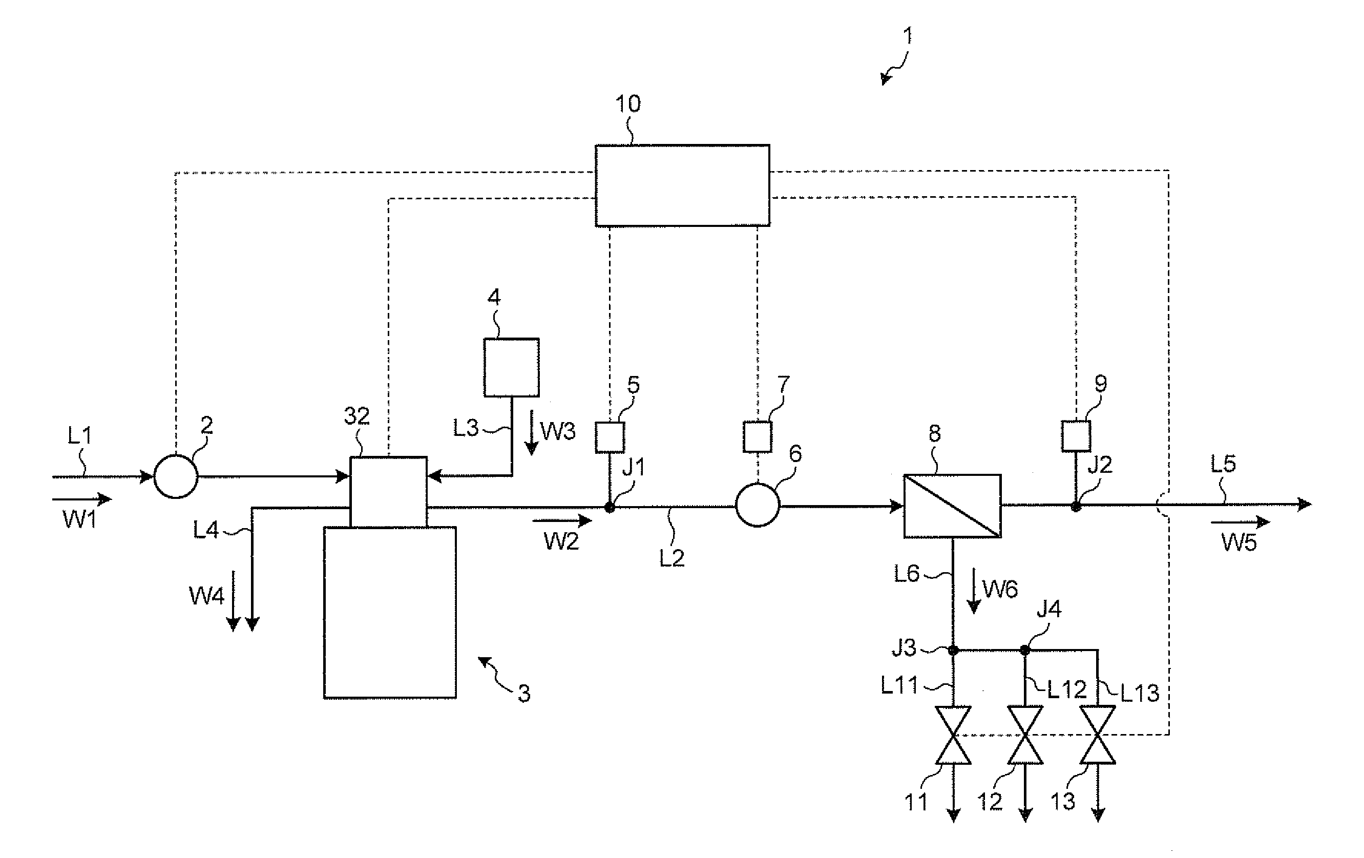
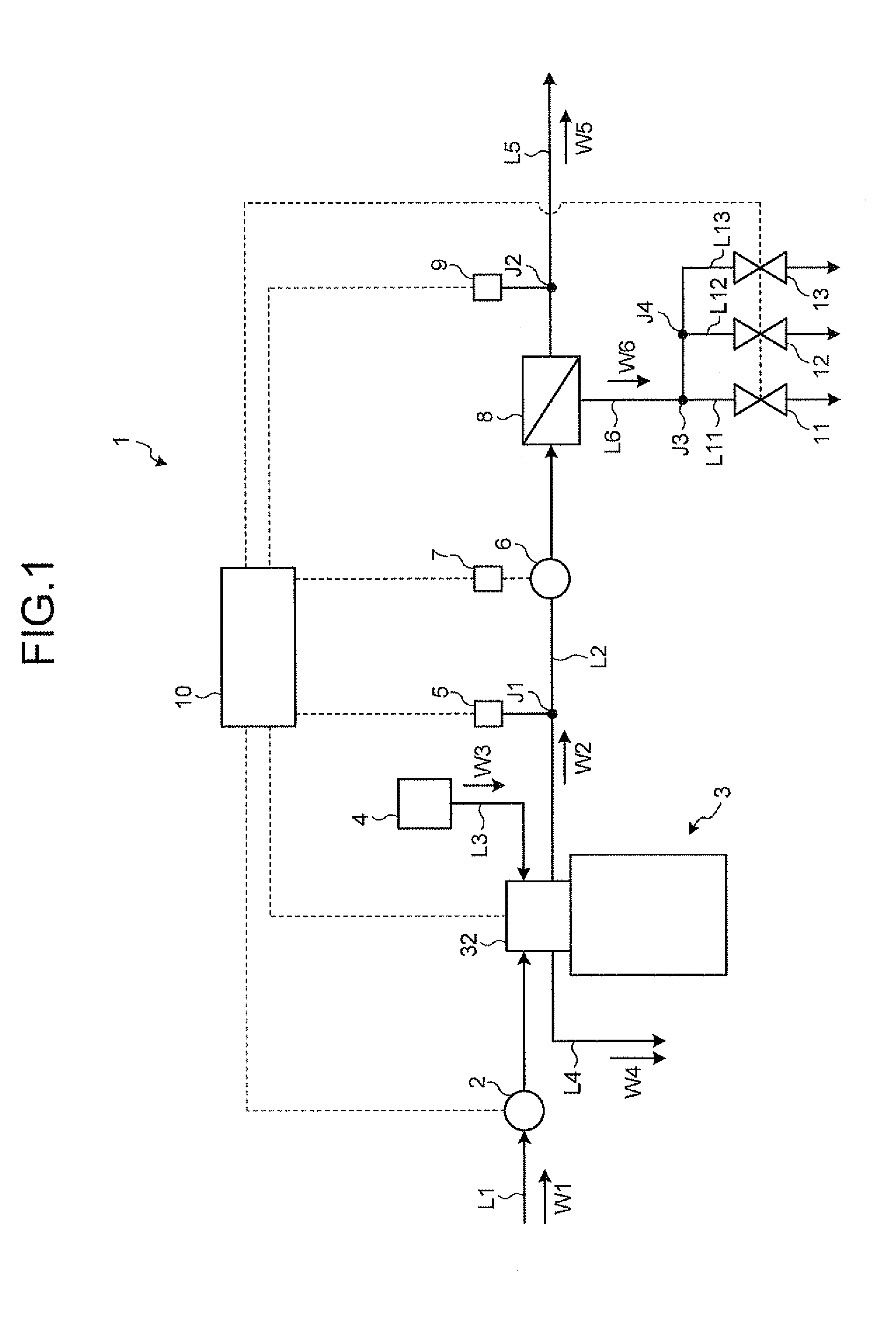
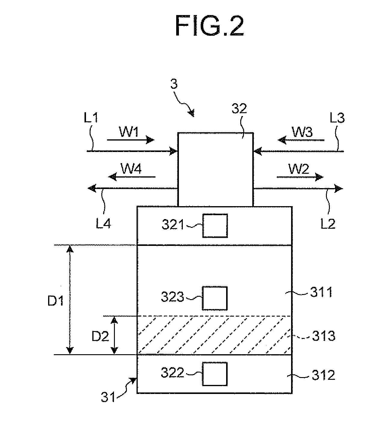
[0024]A water treatment system 1 according to a first embodiment of the present invention is described with reference to the drawings. The water treatment system 1 is applied to a pure water production system that produces pure water from fresh water, for example. FIG. 1 is an overall configuration diagram of the water treatment system 1 according to the first embodiment. FIG. 2 is a schematic cross-sectional view of a water softening device 3. FIG. 3 is a flowchart of a process that is performed by a control unit 10. FIGS. 4A and 4B are explanatory diagrams showing a basic process that is performed by the control unit 10.

[0025]As shown in FIG. 1, the water treatment system 1 according to the first embodiment includes a raw water pump 2, the water softening device 3, a salt water tank 4 as a regenerant supply unit, and a temperature sensor 5 as a temperature detecting unit. The water treatment system 1 further includes a pressure pump 6, an inverter equipment 7, an RO membrane modul...

second embodiment

[0108]A water treatment system 1A according to a second embodiment of the present invention is described with reference to FIG. 7. FIG. 7 is an overall configuration diagram of the water treatment system 1A according to the second embodiment. In the second embodiment, differences from the first embodiment are mainly described. In a description of the second embodiment, configurations that are the same as or equivalent to those in the first embodiment are assigned with the same reference numerals or symbols. In the second embodiment, a description redundant with that of the first embodiment is suitably omitted.

[0109]As shown in FIG. 7, the water treatment system 1A according to the second embodiment includes the raw water pump 2, the water softening device 3, the salt water tank 4, the temperature sensor 5, the pressure tank 6, the inverter equipment 7, and the RO membrane module 8. The water treatment system 1A also includes a control unit 10A, the first drain valve 11 to the third ...

third embodiment

[0142]A water treatment system 1B according to a third embodiment of the present invention is described with reference to FIG. 10. FIG. 10 is an overall configuration diagram of the water treatment system 1B according to the third embodiment. In the third embodiment, differences from the first embodiment are mainly described. In a description of the third embodiment, configurations that are the same as or equivalent to those in the first embodiment and the second embodiment are assigned with the same reference numerals or symbols. In the third embodiment, a description redundant with that of the first embodiment and the second embodiment is suitably omitted.

[0143]As shown in FIG. 10, the water treatment system 1B according to the third embodiment includes the raw water pump 2, the water softening device 3, the salt water tank 4, the temperature sensor 5, the pressure pump 6, the inverter equipment 7, and the RO membrane module 8. The water treatment system 1B also includes a control...


PUM

PropertyMeasurementUnit
electric conductivityaaaaaaaaaa
depth D1aaaaaaaaaa
depthaaaaaaaaaa

Abstract

According to one embodiment, a water treatment system includes: a membrane separation device and a water softening device including a valve unit switching between a softening process in which soft water is obtained by passing raw water through a cation exchange resin bed downward and a regeneration process in which a whole of the cation exchange resin bed is regenerated by generating an opposite flow of a regenerant by supplying the regenerant from both sides of a top portion and a bottom portion of the cation exchange resin bed and collecting a liquid at an intermediate portion of the cation exchange resin bed, and a regenerant supply supplying the regenerant in a volume which gives a regeneration level of 1 to 6 eq/L-R, to a hardness leakage prevention region set in a predetermined depth on the bottom portion of the cation exchange resin bed, in the regeneration process.

Description

CROSS-REFERENCE TO RELATED APPLICATION(S)[0001]This application is based upon and claims the benefit of priority from Japanese Patent Application No. 2011-164360, filed Jul. 27, 2011, the entire contents of which are incorporated herein by reference.FIELD[0002]The present invention relates to a water treatment system.BACKGROUND[0003]In a semiconductor manufacturing process, washing of electronic parts, and washing of medical apparatuses, high-purity pure water that does not contain impurities is used. In general, this type of pure water is produced by processing raw water, such as groundwater and tap water, with a reverse osmosis membrane (hereinafter, also an “RO membrane”).[0004]At the time of producing pure water with an RO membrane, there occurs a phenomenon that a hardness component contained in raw water is precipitated as a scale on a surface of the RO membrane. Further, there also occurs a phenomenon of what is called fouling that a suspended substance (colloidal iron in an ...

Claims


Application Information

Patent Timeline
Patent Type & Authority Applications(United States)
IPC IPC(8): C02F5/00C02F1/44C02F1/28
CPCC02F1/008C02F1/42C02F1/441C02F2001/425C02F2103/04C02F2209/003C02F2303/16C02F2209/02C02F2209/03C02F2209/05C02F2209/055C02F2209/40C02F2209/005B01D61/04B01D61/58C02F1/44
Inventor MANABE, ATSUYUKIWATANABE, HAYATO
Owner MIURA COMPANY LIMITED
Why Eureka
Try Eureka