Biological observation apparatus

A technology for observation devices and living organisms, which can be used in medical science, surgery, diagnosis, etc., and can solve the problems of reduced identification and increased circuit scale

Inactive Publication Date: 2008-05-07
OLYMPUS CORP
View PDF6 Cites 8 Cited by
  • Summary
  • Abstract
  • Description
  • Claims
  • Application Information

AI Technical Summary

Problems solved by technology

Therefore, the image displayed on the monitor does not have a color tone image suitable for observing tissue information of a desired deep part of the living tissue, and the visibility may be reduced.
[0007] In addition, the device described in Japanese Patent Application Laid-Open No. 2003-93336 has the following problems

Method used


Image

  • Biological observation apparatus
  • Biological observation apparatus
  • Biological observation apparatus

Examples


Embodiment 1

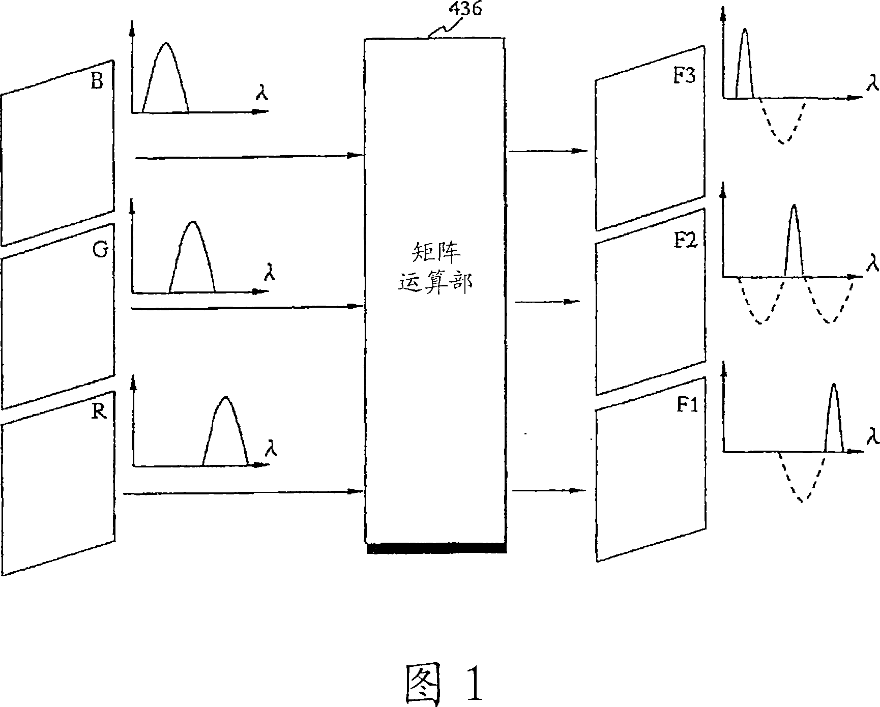
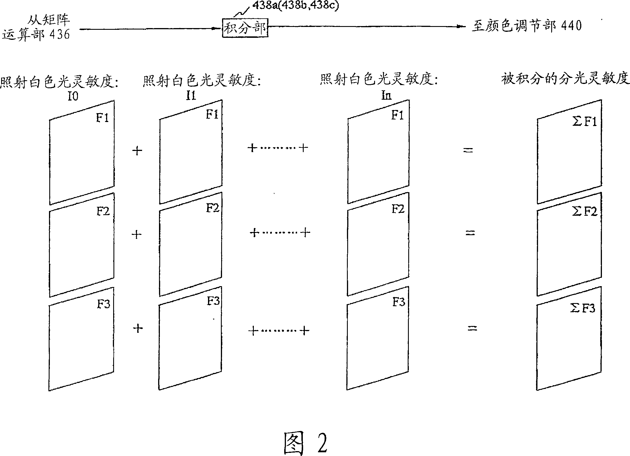
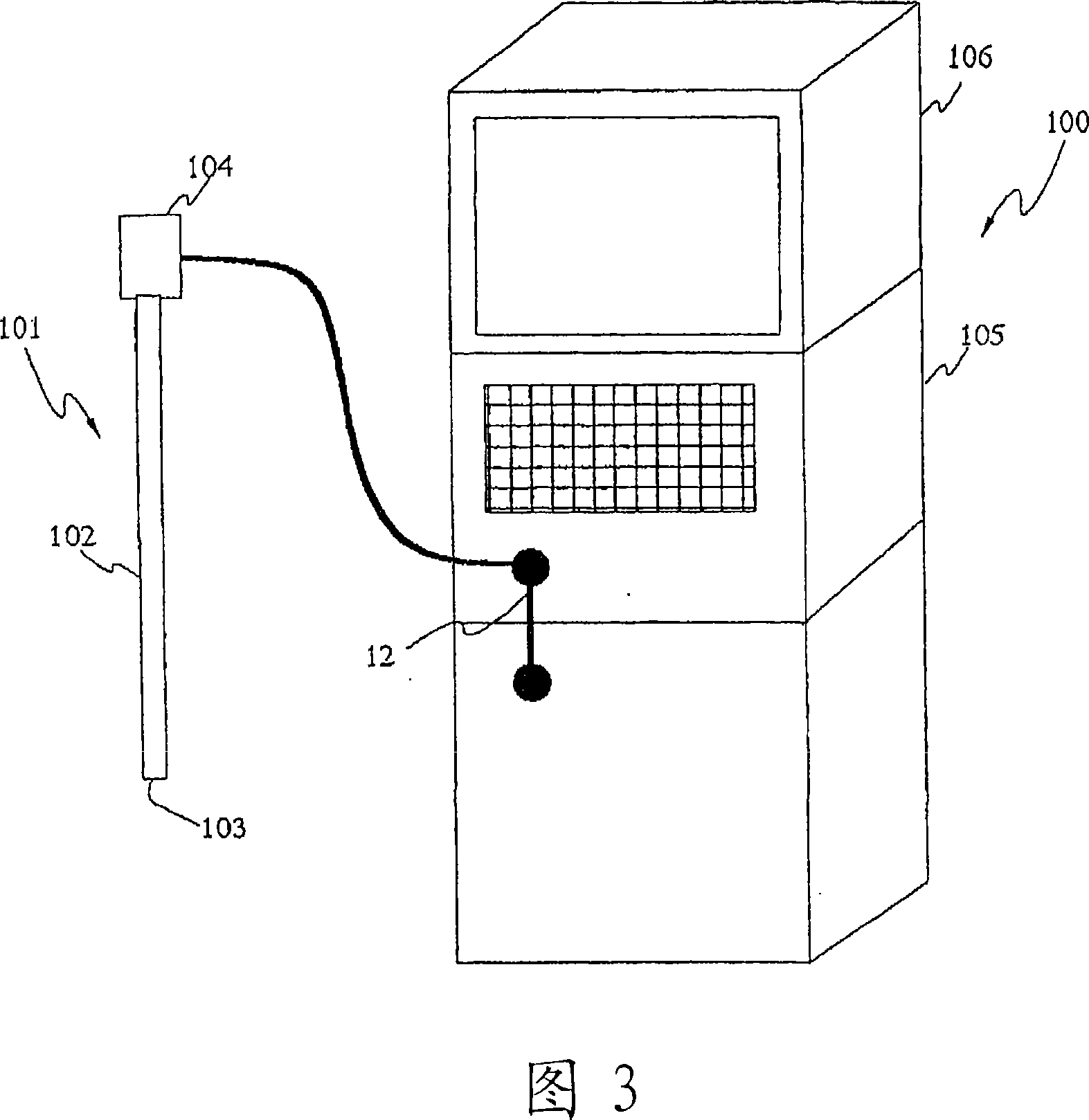
[0075] FIGS. 1 to 26 relate to Embodiment 1 of the present invention. FIG. 1 is a conceptual diagram showing a signal flow when a spectral image signal is generated from a color image signal, and FIG. 2 is a conceptual diagram showing an integration operation of the spectral image signal. , FIG. 3 is an external view showing the appearance of the electronic endoscope device, FIG. 4 is a block diagram showing the structure of the electronic endoscope device of FIG. 3 , and FIG. 5 is an external view showing the external appearance of the shutter of FIG. 4 , FIG. 6 is a diagram showing the arrangement of the color filter arranged on the imaging surface of the CCD of FIG. 3 , FIG. 7 is a diagram showing the spectral sensitivity characteristics of the color filter of FIG. 6 , and FIG. 9 is a spectrogram showing the spectrum of a light source, and FIG. 10 is a spectrogram showing a reflection spectrum of a living body.

[0076] 11 is a diagram showing the layered structure of livin...

Embodiment 2

[0291] FIG. 28 is a block diagram showing the configuration of an electronic endoscope device according to Embodiment 2 of the present invention.

[0292] Since the second embodiment is substantially the same as the first embodiment, only the points different from the first embodiment will be described, and the same components will be given the same reference numerals and their descriptions will be omitted.

[0293] In this embodiment, compared with the first embodiment, the light source unit 41 that controls the amount of illumination light is different. In the present embodiment, the control of the amount of light emitted from the light source unit 41 is performed by controlling the current of the lamp 15 instead of using a shutter. Specifically, the lamp 15 shown in FIG. 28 is provided with a current control unit 18 as a light quantity control unit.

[0294] As the operation of the present embodiment, the control unit 42 controls the current flowing through the lamp 15 so ...

Embodiment 3

[0298]In the living body observation device of FIG. 4 , when acquiring a spectroscopic image, the shutter 16 of FIG. 5 that controls light quantity by blocking light at predetermined time intervals is used to control so as to reduce the light quantity. That is, the amount of light from the light source is reduced so that all color-separated signals of R, G, and B are captured within an appropriate dynamic range.

[0299] In Embodiment 3 of the present invention, an example is described in which movable light-shielding members such as diaphragm springs and shutters, light-shielding filters such as mesh turrets, and ND filters are used instead of the living body observation device of FIG. 4 The shutter 16 in.

[0300] FIG. 29 shows an example of the diaphragm spring 66 . The diaphragm spring 66 controls the amount of light by blocking light at predetermined time intervals by means of the diaphragm blade portion 71 which rotates around the central axis 67 and has a blocking port...


PUM


Abstract

The present invention provides a biometric instrument, which comprises an illuminating unit for illuminating an organism, i.e., a subject, an imaging unit for photoelectrically converting the light of the illuminating light reflected from the organism and generating an imaging signal, and a signal processing control unit for controlling the operation of the imaging section and outputting the imaging signal to a display. The biometric instrument is characterized in that the signal processing control unit includes a spectral signal generating section for generating a spectral signal corresponding to an image in an optical wavelength narrow band from the imaging signal by signal processing, a color adjusting section for assigning color tones different with the bands where the spectral signal is formed when the spectral signal is outputted to the display, and an image quality adjusting section for adjusting the image quality of the signal outputted to the display, or the other signal processing sections than at least the spectral signal generating section and the color tone adjusting section are shared for the signal processings of the imaging signal and the spectral signal.

Description

technical field [0001] The present invention relates to a living body observation device that generates a pseudo (pseudo) narrow-band filter through signal processing using a color image signal obtained by photographing a living body, and displays it as a spectroscopic image on a monitor. Background technique [0002] Conventionally, as a living body observation device, an endoscope device that irradiates illumination light to obtain an endoscopic image of the inside of a body cavity has been widely used. In such an endoscope device, an electronic endoscope having an imaging unit that guides illumination light from a light source device into a body cavity using a light guide or the like to image a subject by using the returned light is used. The imaging signal from the imaging unit is signal-processed by a video processor, and an endoscopic image is displayed on an observation monitor to observe an observation site such as an affected area. [0003] In the case of normal li...

Claims


Application Information

Patent Timeline
IPC IPC(8): A61B1/04A61B1/00A61B1/06G02B23/24G02B23/26
Inventor 后野和弘天野正一高桥智也大岛睦巳
Owner OLYMPUS CORP
Why Eureka
Try Eureka