Multi-facet armchair armrest structure
A technology of armrests and armrest brackets, which is applied to chairs, stools, and other seating furniture, etc., which can solve problems such as difficulty in satisfying various choices of users, and achieve the effect of simple and convenient rotation or movement
- Summary
- Abstract
- Description
- Claims
- Application Information
AI Technical Summary
Problems solved by technology
Method used
Image
Examples
no. 1 example 〕
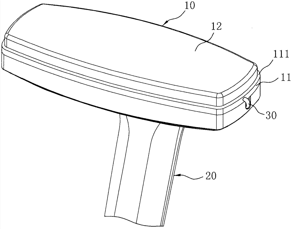
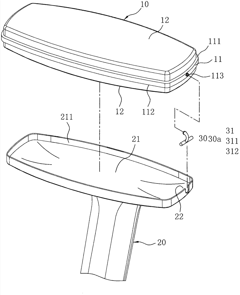
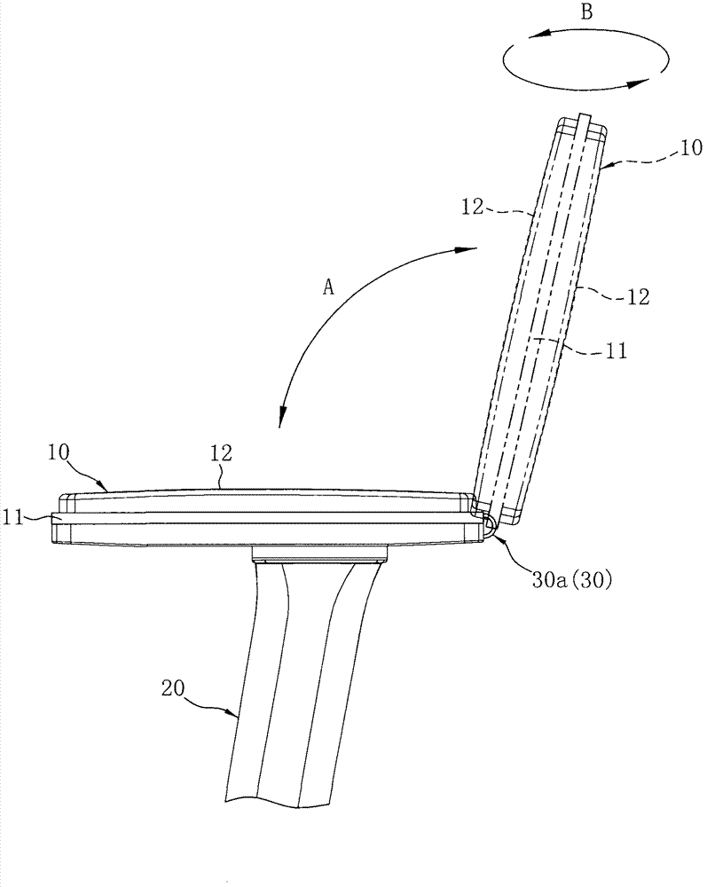
[0030] Please refer to figure 2 and image 3 As shown, the positioning mechanism 30a (30) is a connection type positioning mechanism, the positioning mechanism 30a (30) includes a T-shaped body 31, but not limited, such as I-shaped, one end of the body 31 is pivoted to the armrest One side of the middle portion 11 of the pad 10 and the other end are pivotally connected to one side of the armrest bracket 20. The positioning mechanism 30a (30) enables the armrest pad 10 to pivot out and move in relative to the armrest bracket 20. The armrest pad 10 can also rotate relative to the positioning mechanism 30a (30).
[0031] Please refer to figure 2 As shown, one end of the main body 31 is provided with a first pivot portion 311 and the other end is provided with a second pivot portion 312 , and one side of the middle portion 11 of the armrest pad 10 is provided with a pivot portion 113 to connect with the main body 31 . The first pivoting portion 311 of the armrest bracket 20 i...
no. 2 example
[0034] Please refer to Figure 4Shown is a schematic diagram (front view) of the use state of the multi-faceted chair armrest structure of the present invention. The positioning mechanism 30b (30) is a separate positioning mechanism, and the positioning mechanism 30b (30) includes two male fasteners 32 and two female The clasping members 33 are correspondingly clasped respectively, and the two male clasping members 32 are respectively disposed on the front and rear ends of the armrest bracket 20 (viewed in the direction of the seated person), or the left and right ends (not shown in the figure). ), the two female fasteners 33 are respectively disposed at the front and rear ends (viewed in the direction of the seated person), or the left and right ends (not shown) of the middle portion 11 of the armrest pad 10, and so on The male fastener 32 and the female fastener 33 are in a fastened or open state, so that the armrest pad 10 can be combined or separated from the armrest brack...
no. 3 example
[0037] Please refer to Figure 5 As shown, it is a schematic view (planned) of the use state of the armrest structure of the multi-faceted chair of the present invention. The positioning mechanism 30c ( 30 ) includes two sliding rails 34 and two sliding grooves 35 . The two sliding rails 34 are respectively disposed on the left and right sides of the middle portion 11 of the armrest pad 10 (viewed in the direction of the seated person), and the two sliding grooves 35 are respectively disposed on the left and right inner sides of the armrest bracket 20 ( Viewed from the direction of the seated person), the armrest pad 10 is moved out and in relative to the armrest bracket 20 by such operation; in addition, the setting positions of the two sliding rails 34 and the two sliding grooves 35 can also be interchanged, that is, the two Each sliding rail 34 is arranged on the armrest support 20 (not shown in the figure), and the two sliding grooves 35 are arranged on the middle portion ...
PUM
 Abstract
Description
Claims
Application Information
 - R&D
- Intellectual Property
- Life Sciences
- Materials
- Tech Scout
- Unparalleled Data Quality
- Higher Quality Content
- 60% Fewer Hallucinations
Browse by: Latest US Patents, China's latest patents, Technical Efficacy Thesaurus, Application Domain, Technology Topic, Popular Technical Reports.
© 2025 PatSnap. All rights reserved.Legal|Privacy policy|Modern Slavery Act Transparency Statement|Sitemap|About US| Contact US: help@patsnap.com


