Large bar chamfering machine tool

A machine tool and chamfering technology, which is applied to turning equipment, turning equipment, metal processing equipment, etc., can solve the problems of high labor intensity, high cost of labor, low production efficiency, etc., and achieve compact structure, good safety performance, Adjust the effect of fast speed

Active Publication Date: 2013-03-06
ZHEJIANG JIULI HI TECH METALS
View PDF6 Cites 27 Cited by
  • Summary
  • Abstract
  • Description
  • Claims
  • Application Information

AI Technical Summary

Problems solved by technology

[0002] According to the production process of hot-extruded steel pipes, after the round rods are cut to a certain length, it is necessary to perform internal and external chamfering and turning of large rods with diameters from 140mm to 340mm and lengths from 300mm to 1200mm. It is an ordinary lathe, that is, a general-purpose machine tool on the market. Before processing, use a crane to load the large bar into the machine tool, then manually clamp the three-jaw chuck in sequence, and then perform chamfering and other work. Authorized announcement number CN 201815664 U, The Chinese utility model patent issued on May 4, 2011 in the authorized announcement discloses a horizontal double-sided car end face chamfering machine tool. The existing ordinary machine tool is used for chamfering and car end face. Manual hoisting of large bars takes a long time, has poor safety and low efficiency, and it is easy to cause damage to the large bars during the hoisting process; secondly, it is very inconvenient to clamp the large bars by hand and requires a lot of cost time, the labor intensity of the workers is high, the production efficiency is low, and the safety is poor

Method used


Image

  • Large bar chamfering machine tool
  • Large bar chamfering machine tool
  • Large bar chamfering machine tool

Examples


Embodiment Construction

[0038] The following descriptions are only preferred embodiments of the present invention, and do not limit the scope of the present invention.

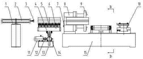
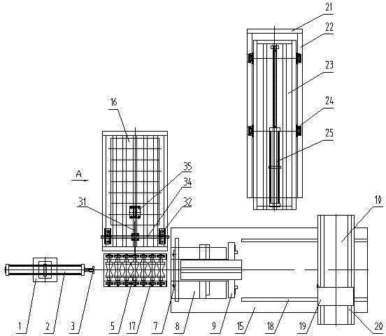
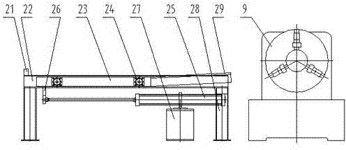
[0039] example, see attached figure 1 , 2 , 3, 4, 5, 6, 7, a large bar chamfering machine tool, including a bed 15, a machine tool headstock 8 mounted on the front end of the bed 15, mounted on the machine tool headstock 8 The three-jaw chuck 9, the headstock of the machine tool 8 is provided with a main shaft through hole, and a semicircular die seat is installed inside the main shaft through hole. The semicircular die seat 7 has various specifications according to the needs of production. 7 corresponds to a blank bar of a certain diameter, and the semi-circular die base 7 with a smaller radius can be set inside the semi-circular die base 7 with a larger radius, layer by layer, and the three-jaw chuck 9 is used to clamp the large bar. When processing a bar of different diameters, first install the corresponding semicircular die se...


PUM

PropertyMeasurementUnit
diameteraaaaaaaaaa
lengthaaaaaaaaaa

Abstract

The invention discloses a large bar chamfering machine tool, comprising a bed body, a machine tool bedside box, a three-claw chuck and transverse guide rails, as well as a loading device, a lifting device, a bar propulsion device and an unloading device, wherein the machine tool bedside box is installed on the front end of the bed body; the three-claw chuck is installed on the machine tool bedside box; the transverse guide rails are installed on the bed body and located behind the machine tool bedside box; a tool tail seat is installed on the transverse guide rails; longitudinal guide rails are arranged on the tool tail seat; the loading device is used for conveying large bars; the lifting device is located ahead of the bed body; the bar propulsion device is arranged ahead of the lifting device as well; and the unloading device is located on the side of the bed body. With the adoption of the chamfering machine tool provided by the invention, the automatic loading and unloading of the large bars are realized, the production efficiency is improved, the labor intensity is decreased, and the safety performance is good; and in addition, the large bar chamfering machine tool is compact in structure, simple to operate, reliable to work and convenient to control, and can effectively adapt to the rapid clamping and processing of the bars with various diameters and lengths.

Description

technical field [0001] The invention relates to the technical field of stainless steel pipe production, in particular to a large bar chamfering machine tool. Background technique [0002] According to the production process of hot extruded steel pipe, after the round bar is cut into a certain length, it is necessary to carry out inner and outer chamfering and turning of the large bar with a diameter from 140mm to 340mm and a length from 300mm to 1200mm. It is an ordinary lathe, that is, a general-purpose machine tool on the market. Before processing, a crane is used to load the large bar into the machine tool, and then the three-jaw chuck is manually clamped in sequence, and then chamfering and other work are performed. Authorization announcement number CN 201815664 U, The Chinese utility model patent issued in the authorization announcement on May 4, 2011 discloses a horizontal double-sided car end face chamfering machine tool. The existing ordinary machine tool is used for...

Claims


Application Information

Patent Timeline
Patent Type & Authority Applications(China)
IPC IPC(8): B23B5/16B23B15/00
Inventor 杜兴吉赵信华沈晓军戴亨涛沈雪林刘向华楼利常
Owner ZHEJIANG JIULI HI TECH METALS
Why Eureka
Try Eureka