Adaptive Limit Hinge

A self-adaptive hinge technology, applied in the field of hinges, can solve problems affecting the actual effect of door opening or closing, and achieve the effects of simple and reasonable structure, extended service life and flexible operation

Active Publication Date: 2015-11-04
伍志勇
View PDF6 Cites 8 Cited by
  • Summary
  • Abstract
  • Description
  • Claims
  • Application Information

AI Technical Summary

Problems solved by technology

Since the linear buffer of this hinge is always connected to the pull rod through the steering element, when closing and opening the door, the door body will be affected by the linear buffer, which will affect the actual effect of opening or closing the door.

Method used


Image

  • Adaptive Limit Hinge
  • Adaptive Limit Hinge
  • Adaptive Limit Hinge

Examples


no. 1 example

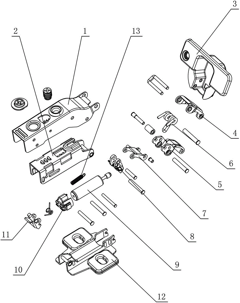
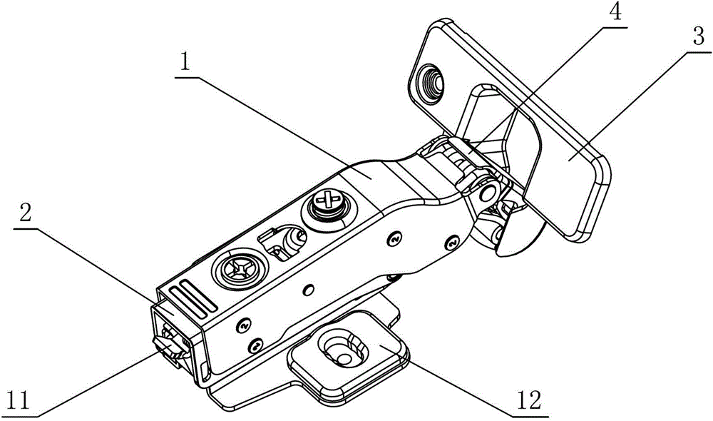
[0029] see figure 1 - Figure 4 , the self-adaptive limit hinge includes a connecting arm 1 and a movable cup holder 3 connected by a rocker arm. The connecting arm 1 is provided with a damper 9, and the hinge is also provided with at least an opening and closing force for the movable cup holder 3. The torsion spring 6 and the damper 9 are self-resetting pressure dampers, and one end is arranged in the connecting arm 1, and the other end is connected with the conversion rod 8 at least during the hinge closing process; the damper 9 and / or the conversion rod 8 are provided with automatic To adapt to the limit mechanism, the two are adaptively limit-cooperated at least during the closing process of the hinge.

[0030] see figure 1 , Figure 4 , the above-mentioned rocker arm includes the outer rocker arm 4 and the inner rocker arm 5, and the torsion spring 6 is positioned at the hinge of the connecting arm 1 and the outer rocker arm 4 through the positioning of the pin; the to...

no. 2 example

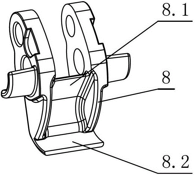
[0034] see Figure 5 , Figure 6 , the self-adaptive limit hinge, the conversion rod 8 is provided with an upper block 8.1, a lower block 8.2 and a convex portion 8.3, the buffer head 9.2 is provided with a concave portion corresponding to the convex portion 8.3, and the damper 9 is connected to the upper block by the buffer head 9.2. The stopper 8.1, the lower stopper 8.2 and the convex part 8.3 are adaptively limited and connected at least during the hinge closing process. Other unmentioned parts are the same as the first embodiment.

no. 3 example

[0036] see Figure 7 , Figure 8 , the self-adaptive limit hinge, the conversion rod 8 is provided with an upper block 8.1, a lower block 8.2 and a concave portion 8.4, the buffer head 9.2 is provided with a convex portion corresponding to the concave portion 8.4, and the damper 9 is connected to the upper block through the buffer head 9.2 The block 8.1, the lower stop block 8.2 and the concave portion 8.4 are adaptively limited and connected at least during the hinge closing process. Other unmentioned parts are the same as the first embodiment.


PUM


Abstract

The invention relates to a self-adaptive limit hinge, which comprises a connecting arm and a movable cup base which are connected through a rocker arm, wherein the connecting arm is provided with a damper, and a torsional spring which at least produces open and close acting force on the movable cup base is arranged in the hinge. The self-adaptive limit hinge is characterized in that the damper is an automatic reset type pressure damper, one end of the damper is arranged in the connecting arm, and the other end of the damper is connected with a change-over lever at least in a closing process of the hinge; and a self-adaptive limit mechanism is arranged on the damper and / or the change-over lever, and the self-adaptive limit mechanism is matched with the damper or the change-over lever in a self-adaptive limit mode at least in the closing process of the hinge. According to the self-adaptive limit hinge disclosed by the invention, the damper and / or the change-over lever are / is provided with the self-adaptive limit mechanism, so that the end part of a piston rod of the damper is matched with the change-over lever in a limit mode at least in the closing process of the hinge, and the piston rod of the damper can not be separated from the change-over lever in the closing process of the hinge; and a joint of the piston rod and the change-over lever is provided with an interval for the movement of the end part of the piston rod, so that the problem that the damper is damaged easily due to the fixed restraint of the damper and the hinge is avoided, and the damper is more flexible in a working process.

Description

technical field [0001] The invention relates to a hinge, in particular to an adaptive limit hinge suitable for furniture. Background technique [0002] Chinese Patent Document No. CN101861441A disclosed a hinge for furniture on October 13, 2010, including: a hinge part that can be fixed on the door or cover, and the hinge part is pivotally supported on the On the side part, wherein the side part is held on the mounting plate that can be installed on the furniture body; at least one spring, by means of which the hinge part is biased towards the closed position in the automatic pull-in range; and the linear buffer, the linear buffer Comprising a piston rod movable relative to the damper housing for damping the closing movement of the hinge parts; the damper is formed as a pressure damper and is provided with a deflection element which is coupled to the damper and when closing the hinge part Can be moved via a tie rod; the deflection element is mounted rotatably on the side pa...

Claims


Application Information

Patent Timeline
Patent Type & Authority Patents(China)
IPC IPC(8): E05F3/20E05D11/06E05D11/10
Inventor 伍志勇
Owner 伍志勇
Why Eureka
Try Eureka