Rotary compressor with compression pump separated from motor

A rotary compressor and compression pump technology, applied in the field of compressors, can solve problems such as motor overload capacity and adverse effects on reliability, direct contact with refrigerant, potential safety hazards, etc., to improve the safety and reliability of use, The effect of large allowable speed range and high return air temperature

Active Publication Date: 2015-04-22
GREE ELECTRIC APPLIANCES INC +1
View PDF5 Cites 0 Cited by
  • Summary
  • Abstract
  • Description
  • Claims
  • Application Information

AI Technical Summary

Problems solved by technology

Since the high-temperature and high-pressure refrigerant directly contacts the motor and other components in the closed shell, the high-temperature and high-pressure exhaust will have an adverse effect on the overload capacity and reliability of the motor; The use of some environmentally friendly refrigerants with flammable and explosive properties, such as hydrocarbon refrigerants, is restricted due to potential safety hazards.

Method used


Image

  • Rotary compressor with compression pump separated from motor
  • Rotary compressor with compression pump separated from motor
  • Rotary compressor with compression pump separated from motor

Examples


Embodiment 1

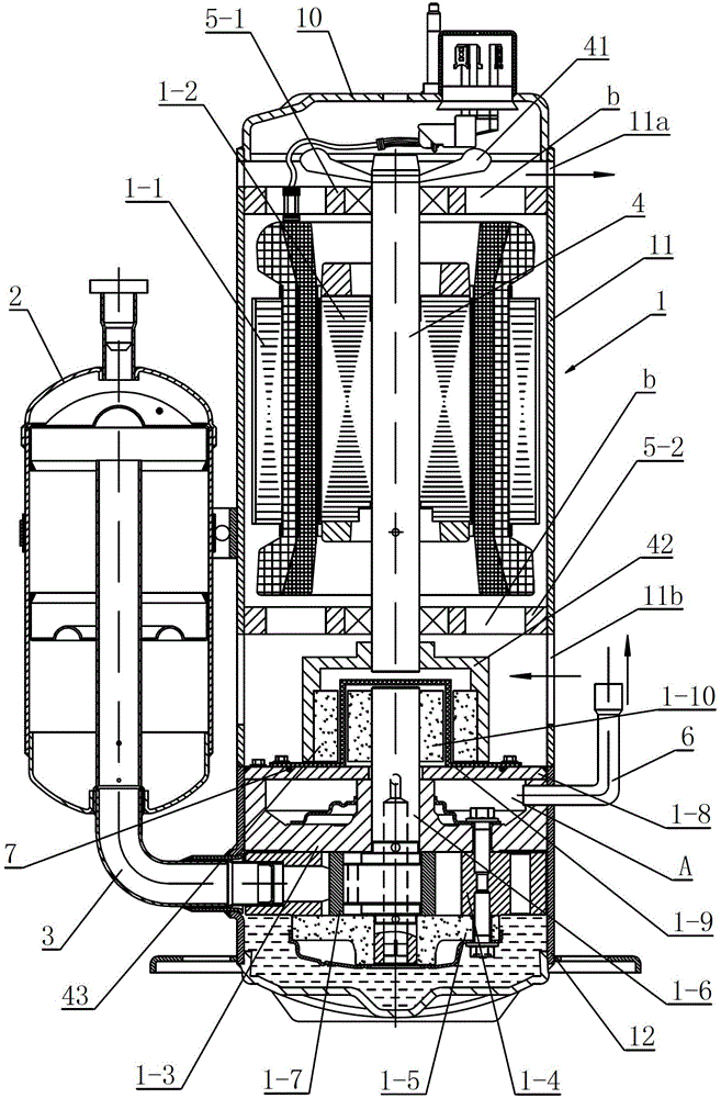
[0027] Such as figure 1 As shown, the rotary compressor of the present invention includes a closed casing 1, a motor and a compression pump body arranged inside the closed casing 1, a gas-liquid separator 2 arranged on one side of the closed casing 1, and a gas-liquid separator 2 The intake elbow 3 communicates with the compression pump body of the compressor, so that the refrigerant enters the cylinder of the compressor from the gas-liquid separator 2 . For ease of description, the figure 1 Up and down are defined by the axial direction of the rotating shaft 4 of the middle compressor.

[0028] The motor of the present invention includes a stator 1-1 fixed on the upper inner wall of the closed casing 1 and a rotor 1-2 rotatably arranged in the stator 1-1, and the compressor shaft 4 is driven to rotate by the rotor 1-2. The compression pump body is arranged in the closed casing 1 and is located below the motor. The upper and lower sides of the motor in the closed housing 1 ...

Embodiment 2

[0037] The difference between this embodiment and Embodiment 1 is that the outer magnetic steel 43 of this embodiment is directly installed on the lower end of the compressor shaft 4, and the isolation sleeve 1-9 isolates the outer magnetic steel 43 from the inner magnetic steel 1-10, When the outer magnetic steel 43 rotates, the inner magnetic steel 1-10 and the outer magnetic steel 43 rotate synchronously due to the magnetic force, driving the pump body rotating shaft 1-6 to rotate, thereby compressing the refrigerant in the cylinder.

Embodiment 3

[0039] The difference between this embodiment and Embodiment 1 lies in that the installation positions of the inner magnet, the outer magnet and the magnet sleeve are just opposite. In this embodiment, the inner magnetic steel 1-10 is installed on the lower end of the compressor rotating shaft 4, the spacer sleeve 1-9 is fixed on the lower bearing bracket 5-2, and the inner magnetic steel 1-10 is covered therein. The outer magnetic steel 43 is installed on the upper end of the pump body rotating shaft 1-6 through the magnetic steel sleeve 42, and is located above the pump body cover plate 1-8. When the rotating shaft 4 of the compressor rotates, the inner magnetic steel 1-10 drives the outer magnetic steel 43 to rotate synchronously, so that the rotating shaft 1-6 of the pump body rotates together, thereby compressing the refrigerant in the cylinder.


PUM


Abstract

A rotary compressor with compression pump separated from motor comprises an inside motor and a seal shell for the compression pump, a compressor rotary shaft, and a gas-liquid separator communicating with the compression pump through an intake elbow pipe. The compression pump comprises an upper flange, a cylinder and a lower flange; the compressor rotary shaft is driven by a motor to rotate; the upper flange, the cylinder and the lower flange are successively arranged on a pump rotary shaft with an axis coinciding with that of the compressor rotary shaft; the pump rotary shaft is driven by the compressor rotary shaft to rotate; a pump cover plate fixed on an inner wall of the seal shell is arranged above the upper flange; the pump cover enables the space in the seal shell and below the pump cover plate to form a sealed high-pressure area; an exhaust pipe communicating with the high-pressure area is arranged on a side wall of the seal shell; and radiating holes are arranged on a peripheral wall of the seal shell and above the pump cover plate. According to the invention, electrical components are separated from a refrigerant, so as to improve usage safety and reliability of the compressor.

Description

technical field [0001] The invention belongs to the technical field of compressors, in particular to a rotary compressor in which a compression pump body and a motor are separated. Background technique [0002] A hermetic rotary compressor used in household appliances such as air conditioners usually includes a closed casing, a motor, a compressor shaft, a compression pump body, a gas-liquid separator, a suction pipe, and an exhaust pipe. Wherein, the motor is composed of a stator and a rotor, and the compression pump body communicates with the gas-liquid separator through a connecting pipe. The compression pump body in the compressor plays the role of compressing the refrigerant, which is used to suck and compress the refrigerant, and then output the high-temperature and high-pressure refrigerant. The compression pump body of the compressor usually includes cylinders, rollers, upper flanges, lower flanges and sliding vanes. The compression pump body is installed under the...

Claims


Application Information

Patent Timeline
Patent Type & Authority Patents(China)
IPC IPC(8): F04C29/00
Inventor 林少坤陈炯
Owner GREE ELECTRIC APPLIANCES INC
Why Eureka
Try Eureka