
Voltage regulation valve

A technology of pressure-stabilizing valve and valve body, applied in the field of pressure-stabilizing valve, can solve the problems of pipeline impact, pipe burst, high manufacturing cost, etc.

Inactive Publication Date: 2013-03-06
CHANGZHOU TIANXU ELECTROMECHANICAL MFG
View PDF5 Cites 9 Cited by
  • Summary
  • Abstract
  • Description
  • Claims
  • Application Information

AI Technical Summary

Problems solved by technology

This requires a good control of the pressure in the pipeline. When the pressure in the pipeline is too high, if the pipeline is continuously pressurized, it will cause impact on the pipeline and cause a pipe burst accident, which will affect the safety of transportation. This requires a A valve that can control the pressure of the fluid in the pipeline to control the pressure of the pipeline
Most of the existing pressure stabilizing valves use electric control to control the flow and velocity, which has complex structures, cumbersome control procedures and high manufacturing costs.

Method used


Image

  • Voltage regulation valve
  • Voltage regulation valve

Examples


Embodiment Construction

[0011] The present invention is described in further detail below in conjunction with the embodiment that accompanying drawing provides.

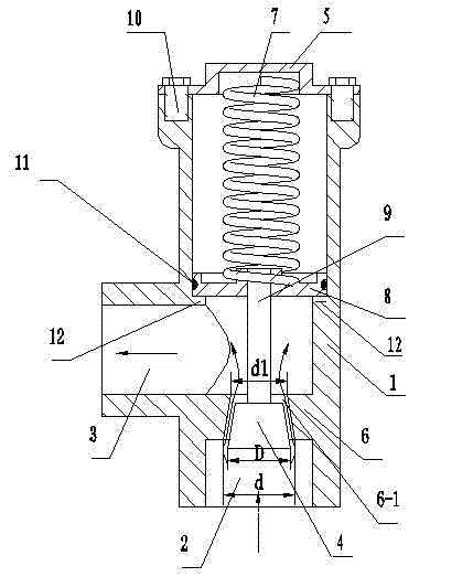
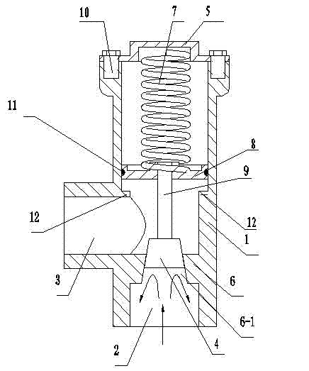
[0012] Such as figure 1 , 2 As shown, a pressure stabilizing valve of the present invention has a valve body 1, a liquid inlet 2 and a liquid outlet 3 are provided on the valve body 1, and a valve core 4 is housed in the valve body 1, and it is characterized in that: the valve body 1 The liquid inlet 2 on the top is connected vertically with the liquid outlet 3, and the top of the valve body 1 is fixedly connected with an upper cover 5; the liquid inlet 2 of the valve body 1 has a baffle plate 6, and the baffle plate 6 has a tapered hole 6-1, the inner surface of the upper cover 5 is in contact with one end of the spring 7, and the valve body 1 is also provided with a spring seat 8, and the other end of the spring 7 is in contact with the spring seat 8; the spring seat 8 is connected through the connecting rod 9 is fixedly connected with ...


PUM


Abstract

The invention discloses a voltage regulation valve, which comprises a valve body, wherein a liquid inlet and a liquid outlet are arranged in the valve body, and a spool is arranged in the valve body. The voltage regulation valve has the innovative points that the liquid inlet and the liquid outlet in the valve body are vertically communicated with each other, and the top end of the valve body is fixedly connected with an upper cover; a baffle is arranged at the liquid inlet of the valve body, and a tapered hole is arranged in the baffle; the inner surface of the upper cover is propped against one end of a spring, and a spring seat is also arranged in the valve body; the other end of the spring is propped against the spring seat, and the spring seat is fixedly connected with the spool through a connecting rod; and the spool is a frustoconical body and slides in the tapered hole, and the diameter D of the lower bottom surface of the frustoconical body is greater than the small inner diameter d1 of the tapered hole and is smaller than the large inner diameter d of the tapered hole. The voltage regulation valve provided by the invention has the characteristics of simple structure and low production cost.

Description

technical field [0001] The invention relates to a valve, in particular to a pressure stabilizing valve for stabilizing medium flow. Background technique [0002] At present, during the transportation of fluids, pipeline connections are used for transportation. This requires a good control of the pressure in the pipeline. When the pressure in the pipeline is too high, if the pipeline is continuously pressurized, it will cause impact on the pipeline and cause a pipe burst accident, which will affect the safety of transportation. This requires a A valve that can control the pressure of the fluid in the pipeline is used to control the pressure of the pipeline. Most of the existing pressure stabilizing valves use electric motors to control the flow and velocity, and their structures are complex, the control procedures are cumbersome, and the manufacturing cost is high. Contents of the invention [0003] The purpose of the present invention is to provide a pressure stabilizing...

Claims


Application Information

Patent Timeline
IPC IPC(8): F16K17/30
Inventor 王红宽
Owner CHANGZHOU TIANXU ELECTROMECHANICAL MFG
Learn More