
Rotary valve with the actuator and the actuator of the rotary valve

A technology for actuators and rotary valves, applied in the direction of cocks including cut-off devices, valve operation/release devices, valve details, etc., to achieve space-saving effects

Active Publication Date: 2013-03-06
KITZ CORP
View PDF10 Cites 2 Cited by
  • Summary
  • Abstract
  • Description
  • Claims
  • Application Information

AI Technical Summary

Problems solved by technology

As a result, the actuator becomes an extended shape in the lateral direction, and the overall size becomes larger

Method used


Image

  • Rotary valve with the actuator and the actuator of the rotary valve
  • Rotary valve with the actuator and the actuator of the rotary valve
  • Rotary valve with the actuator and the actuator of the rotary valve

Examples


Embodiment Construction

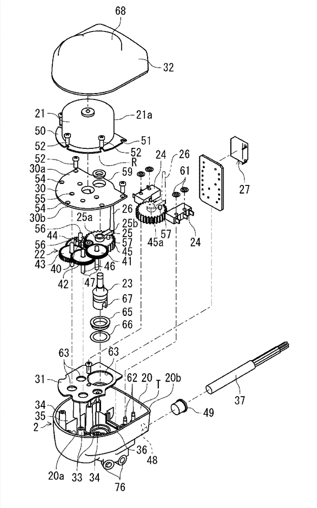
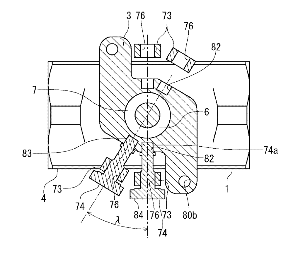
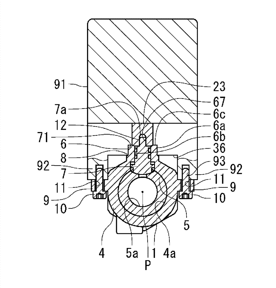
[0090] Embodiments of the rotary valve with an actuator and the actuator of the rotary valve according to the present invention will be described in detail below with reference to the drawings. figure 1 An isolated perspective view showing a rotary valve with an actuator of the present invention, image 3 , Image 6 Indicates the connection status of the valve and actuator, Figure 17 An isolated perspective view showing the actuator.

[0091] In the figure, the rotary valve with an actuator of the present invention has a valve 1 , an actuator body 2 , and a connecting plate 3 , and the valve 1 and the actuator body 2 are detachable via the connecting plate 3 . The rotary valve with an actuator of the present invention is arranged, for example, in various types of equipment not shown in the drawings, or in a part of devices, as an automatic operation valve.

[0092] like figure 2 As shown, the valve 1 is, for example, a rotary valve structure composed of a ball valve as s...


PUM


Abstract

The present invention provides a rotary with an actuator, being able to achieve compactness and to assemble compactly and achieve miniature of a device, realizing space-saving, being able to be configured in the settings in the narrow place without processing precision and the adjustment of the flow to the position relationship between valve and actuator to established high precision and easy to dismount, and provides an actuator with a rotary valve being able to ensure compactness with the necessary minimum number of parts and ensure excellent visual identity and being able to easily confirm the valve opening. Through the valve rod (7) that is built into the subject body (5), (4) using the actuator (2) make the valve rod rotation. With in the main body of the valve rod shaft side of the outer top face (8) fixed on the connecting plate body (3), carrying actuator on the connection plate body, and using the connecting mechanism (90) set the valve and actuator (1) ontology is able to tear open outfit, described by connecting mechanism from the transverse direction of the axis of the stem cross plug off the fixed body composition.

Description

technical field [0001] The present invention relates to a rotary valve with an actuator that is excellent in compactness as a small electric valve that can be incorporated into equipment or the like, and an actuator that is integrally mounted on the rotary valve and can be downsized. Background technique [0002] Conventionally, as a rotary valve with an actuator in which an actuator is mounted on a valve, for example, an electric ball valve disclosed in Patent Document 1 is known. Patent Document 1 describes a ball valve in which two legs are extended from the lower part of the electric actuator, and the bolt hole passing through the legs and the protruding part formed on the bonnet of the ball valve pass through the ball valve. A set screw is threaded at the thread to fix the ball valve and the electric actuator. [0003] Patent Document 2 discloses a connection structure in which the valve and the actuator are connected via a yoke member, and a bolt is screwed into the b...

Claims


Application Information

Patent Timeline
Patent Type & Authority Applications(China)
IPC IPC(8): F16K31/00F16K31/04F16K31/53F16K31/524F16K37/00F16K27/00F16K27/10
CPCF16K5/06F16K27/067F16K31/041F16K31/535F16K37/00
Inventor 小菅博之风间正裕清水靖
Owner KITZ CORP
Learn More