
Pneumatic valve

A technology for pneumatic valves and valve switches, applied in the field of connectors and pneumatic valves, can solve the problems of easy loosening of the connection between the valve switch plate and the valve switch plate mounting bracket, poor reliability of opening and closing performance, and short service life. Good performance reliability, reliable opening and closing performance, and long service life

Inactive Publication Date: 2013-03-06
JIANGSU CHANGJING ENVIRONMENTAL PROTECTION TECH
View PDF0 Cites 4 Cited by
  • Summary
  • Abstract
  • Description
  • Claims
  • Application Information

AI Technical Summary

Problems solved by technology

When the valve switch plate completely covers the valve switch plate, the valve is completely closed and the pipes on both sides of the valve are blocked. The valve also has the following defects: (1) Due to the frequent opening and closing of the valve, the cover plate structure of the valve switch plate makes the connection between the valve switch plate and the valve switch plate mounting bracket easy to loose, and even the valve switch plate will be installed from the valve switch plate The bracket falls off, which is easy to damage, has a short service life, and needs frequent replacement and maintenance; (2) The sealing is not good, and the reliability of the opening and closing performance is poor; (3) The valve switch plate and the valve switch plate mounting bracket are made of iron plates, which are easy to break Rust and corrosion, in order to prevent rust and corrosion, it needs to be treated with paint, which increases the production process and production; (3) The valve operation is manual operation, which is time-consuming and laborious, and troublesome to open and close

Method used


Image

  • Pneumatic valve
  • Pneumatic valve
  • Pneumatic valve

Examples


Embodiment

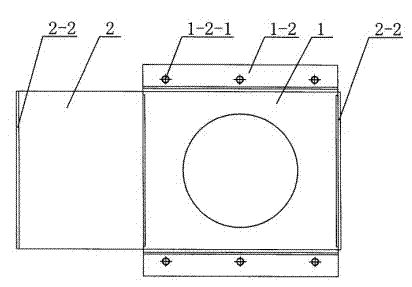
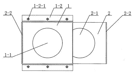
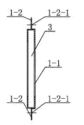
[0017] Such as Figure 1 to Figure 4 As shown, a pneumatic valve includes a valve switch plate mounting bracket 1 and a valve switch plate 2 , and also includes a cylinder 4 . There are bracket through holes 1-1 on the valve switch plate mounting bracket 1, the valve switch plate mounting bracket 1 is a quadrilateral frame with a plate gap 3, and the upper and lower sides of the valve switch plate mounting bracket 1 are provided with bracket through holes 1 -1, the two sides of the valve switch plate mounting bracket 1 are provided with flanges 1-2, the valve switch plate 2 has a valve switch hole 2-1, and the valve switch plate 2 is inserted into the plate gap of the valve switch plate mounting bracket 1 within 3. Both ends of the valve switch plate 2 are provided with protruding valve switch plate trailing edges 2-2. The cylinder 4 is arranged on the valve switch plate mounting bracket 1, and the front end of the piston rod 4-1 of the cylinder 4 is connected with the valve...


PUM


Abstract

The invention relates to a pneumatic valve. The pneumatic valve comprises a valve switch board mounting support (1), a valve switch board (2) and a cylinder (4), the valve switch board mounting support (1) is provided with a support through hole (1-1) and is a quadrilateral frame provided with an insertion board gap (3), the upper surface and the lower surface of the valve switch board mounting support (1) are respectively provided with a support through hole (1-1), flange edges (1-2) are arranged on two sides of the valve switch board mounting support (1), the valve switch board (2) is provided with a valve switch hole (2-1) and is inserted into the insertion board gap (3) of the valve switch board mounting support (1), the cylinder (4) is arranged on the valve switch board mounting support (1), and the front end of a piston rod (4-1) of the cylinder (4) is connected with the valve switch board (2). The pneumatic valve is simple in structure, good in sealability, reliable in switching performance, long in service life and capable of achieving automatic switching.

Description

technical field [0001] The invention relates to a connecting piece used on a material conveying pipeline, in particular to a pneumatic valve. The invention belongs to the technical field of mechanical equipment manufacturing and processing. Background technique [0002] In various equipment for conveying materials such as pneumatic conveying, the pipeline switch control part is an indispensable and important part of the conveying pipeline. The valve is a kind of pipeline switch control part that is widely used. At present, there is a valve whose structure includes a valve switch plate mounting bracket and a valve switch plate. The valve switch plate mounting bracket has a bracket through hole, and the valve switch plate is a cover plate. Type structure, the valve switch plate is connected to the valve switch plate mounting bracket through the pin shaft, etc. When in use, the valve is installed on the connecting pipe through the valve switch mounting bracket. When the valve...

Claims


Application Information

Patent Timeline
Patent Type & Authority Applications(China)
IPC IPC(8): F16K31/12F16K3/02F16K3/30
Inventor 沈鑫森
Owner JIANGSU CHANGJING ENVIRONMENTAL PROTECTION TECH
Learn More