Automatic restoring circuit for groove signals of contactless card

An automatic recovery, non-contact technology, applied in the direction of instruments, inductive record carriers, computer components, etc., can solve problems such as communication errors, misadjustments, and failure to communicate normally

Inactive Publication Date: 2013-03-06
SHANGHAI HUAHONG INTEGRATED CIRCUIT
View PDF4 Cites 9 Cited by
  • Summary
  • Abstract
  • Description
  • Claims
  • Application Information

AI Technical Summary

Problems solved by technology

In this way, if the RF (radio frequency) demodulation circuit is compatible with two types of interfaces, in typeA mode, it is likely to cause misadjustment due to changes in the signal amplitude on the antenna, such as sudden changes in field strength, or when multiple cards are anti-collision. It may cause the RF demodulation circuit to mistakenly treat it as a normal signal for demodulation, resulting in subsequent communication errors, or even failure to communicate normally

Method used


Image

  • Automatic restoring circuit for groove signals of contactless card

Examples


Embodiment Construction

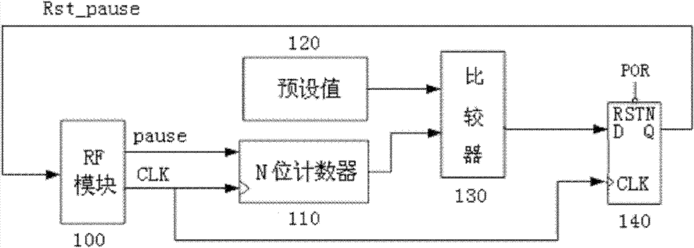
[0015] Referring to the drawings, in one embodiment, the contactless card groove signal automatic recovery circuit includes: RF module 100, N-bit counter 110, preset value module 120, comparator 130, data latch 140 .

[0016] The RF module 100 is used to send and receive RF signals and recovered clock signals with data information. After demodulation is completed, the received signal encoded according to the ISO14443 communication protocol is sent to the N-bit counter 110; The flag signal obtained at the output terminal Q performs a reset operation on the groove signal Pause, so that the groove signal returns to a correct high level. The RF radio frequency signal is based on the ISO / IEC14443 Type A or Type B interface.

[0017] N-bit counter 110, its clock input end is connected with the clock output end of the RF module 100, and its count input end is connected with the groove signal Pause output end of the RF module 100, using the RF module 100 recovered The clock signal C...


PUM


Abstract

The invention discloses an automatic restoring circuit for groove signals of a contactless card. The automatic restoring circuit comprises an RF (radio frequency) module, an N-bit counter, a preset value module, a comparer and a data latch, wherein the RF module is used for receiving radio frequency signals and restoring clock signals which include data information; the N-bit counter is used for counting low-level duration time of the groove signals outputted by the RF module; the preset value module is used for presetting a maximum tolerable low-level duration time value of the groove signals; the comparer is used for comparing an output value of the counter with the preset value, and outputting a marking signal when the output value is equal to the preset value; and the data latch is used for sampling the marking signal outputted by the comparer, obtaining the marking signal at the output end Q of the comparer and enabling the RF module to restore by the aid of the marking signal so as to enable the groove signals to restore to the correct high level. The groove signals can restore to the correct high level to enable subsequent communication to be proceeded normally when the groove signals are overlength.

Description

technical field [0001] The invention relates to the field of non-contact cards, in particular to a non-contact card groove signal automatic recovery circuit. Background technique [0002] Data transmission systems are well known and widely used to exchange information and conduct transactions with remotely located portable data devices. Said portable data device is usually called a card, smart card or tag. Likewise, data sending systems are often referred to as card readers. The transaction begins when the card enters the energizing zone of the reader. Specifically, a card reader (terminal) generates a power signal and a data signal (information signal), and transmits the data signal using a carrier signal. Detection and reception of the carrier signal remotely powers the card and enables the card to perform its intended function. [0003] Remotely powered (ie, contactless) data devices (ie, cards) can be used to perform a variety of tasks, including theft prevention, pe...

Claims


Application Information

Patent Timeline
Patent Type & Authority Applications(China)
IPC IPC(8): G06K7/00
Inventor 覃钧彦
Owner SHANGHAI HUAHONG INTEGRATED CIRCUIT
Why Eureka
Try Eureka