Automatic production system of rotor

A production system and rotor technology, applied in the field of automation systems, can solve problems such as low efficiency, inability to use, poor practical performance, etc., and achieve the effects of accurate work efficiency, reduced use of manpower, and high work efficiency

Inactive Publication Date: 2014-11-26
浙江薪人机电科技有限公司
View PDF3 Cites 0 Cited by
  • Summary
  • Abstract
  • Description
  • Claims
  • Application Information

AI Technical Summary

Problems solved by technology

Extruding the rotating shaft by the above method can easily lead to misalignment between the commutator, the rotating shaft and the end plate, and manual operation is time-consuming and labor-intensive, and the work efficiency is not very high.
[0005] At present, the rotating shaft that has pressed the commutator is sent into the paper inserting machine mainly through manual operation, which is time-consuming and labor-intensive, resulting in low efficiency. At present, there is also a machine that uses a robot arm to grab the rotating shaft, but this kind of machine It rotates around a fulcrum. When the commutator pressing machine on one side of the machine is not on the same level as the operating table of the paper inserting machine, such a machine cannot be used because the fulcrum cannot be adjusted, resulting in a comparison of its practical performance. Difference

Method used


Image

  • Automatic production system of rotor
  • Automatic production system of rotor
  • Automatic production system of rotor

Examples


Embodiment Construction

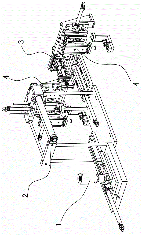
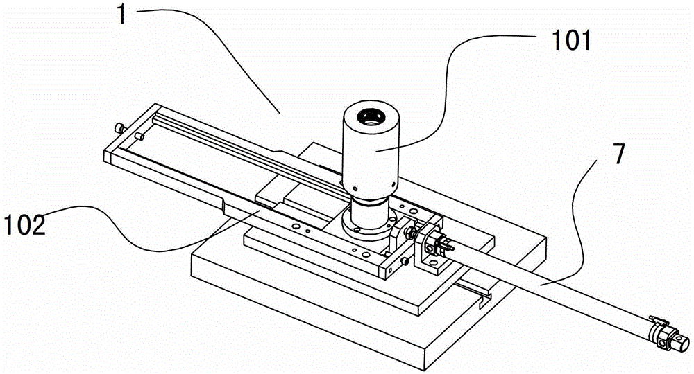
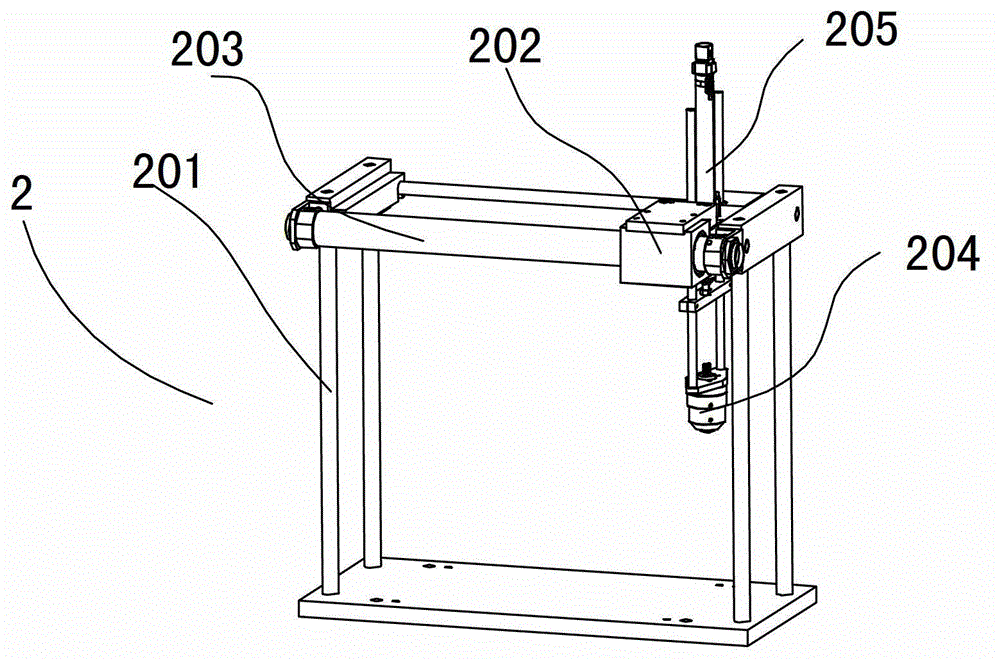
[0043]The rotor automatic production system includes a shaft pressing machine, an end plate pressing device, a commutator pressing device, a paper insertion machine, and a control device. The shaft pressing machine and the paper insertion machine are common mechanisms, so they are not shown in the figure. shown in the figure; the rotating shaft pressing machine is installed in front of the end plate pressing device, and the end plate pressing device includes an end plate pressing mechanism 4 and a rotating shaft rotation fixing mechanism 3; two end plate pressing mechanisms 4 are arranged symmetrically on the rotating shaft Both sides of the fixing mechanism 3; the commutator press-in device, including the commutator material guide mechanism 10, the commutator press-in mechanism 15, the rotating shaft rotation fixing mechanism 3, and the support seat 18; the movement of the commutator material guide mechanism 10 The end of the stroke just corresponds to the start end of the mov...


PUM


Abstract

The invention discloses an automatic production system of a rotor, which comprises a spindle pressing machine, an end plate pressing device, a commutator pressing device, a paper inserting machine and a control device. The spindle pressing machine is arranged in front of the end plate pressing device; the end plate pressing device comprises two end plate pressing mechanisms and a spindle rotation fixing mechanism; the two end plate pressing mechanisms are symmetrically arranged on two sides of the spindle rotation fixing mechanism; the commutator pressing device comprises a commutator feeding mechanism, a commutator pressing mechanism, a spindle rotation fixing mechanism and a supporting seat; a motion displacement tail end of the commutator feeding mechanism corresponds to a motion displacement starting end of the commutator pressing mechanism, a motion displacement tail end of the commutator pressing mechanism corresponds to a motion displacement starting end of the spindle rotation fixing mechanism, wherein the supporting seat is arranged below the motion displacement tail end; and the control device is connected with all mechanisms. The automatic production system of the rotor can achieve the technical aims that an end plate and a commutator are installed on a spindle accurately and equipment floor area is reduced.

Description

technical field [0001] The invention relates to an automatic system for producing micro-motor rotors. Background technique [0002] The rotor on the micro-motor includes the rotating shaft, iron core group, end plate, commutator, insulating sheet and other components. At present, there are manual and automatic production methods for the production of rotors. The manual method is to squeeze the iron core group, end plate, commutator, insulating sheet and other components into the rotating shaft through the extruder in sequence, because the position between the iron core group, end plate, commutator, and insulating sheet has requirements It cannot be placed casually, so that the rotor produced by manual methods may not correspond to the position of each part and cause the product to be unqualified. The automatic production method is to set up a long product production line. Next to the production line is placed equipment that squeezes components such as core groups, end plate...

Claims


Application Information

Patent Timeline
Patent Type & Authority Patents(China)
IPC IPC(8): B23P23/04H02K15/02
Inventor 朱武军郑灿根秦进飞
Owner 浙江薪人机电科技有限公司
Why Eureka
Try Eureka