Control circuit, power supply device and method for controlling power supply

A technology for controlling circuits and circuits, applied to control/regulation systems, output power conversion devices, electrical components, etc., can solve problems such as insufficient guarantee of phase margin, and achieve the effect of sufficient phase margin

Active Publication Date: 2016-01-20
SOCIONEXT INC
View PDF4 Cites 0 Cited by
  • Summary
  • Abstract
  • Description
  • Claims
  • Application Information

AI Technical Summary

Problems solved by technology

However, if the equivalent series resistance ESR value of the ceramic capacitor is too low, the phase margin may not be sufficiently secured

Method used


Image

  • Control circuit, power supply device and method for controlling power supply
  • Control circuit, power supply device and method for controlling power supply
  • Control circuit, power supply device and method for controlling power supply

Examples


Embodiment Construction

[0027] Refer below Figure 1 to Figure 6 An embodiment is described.

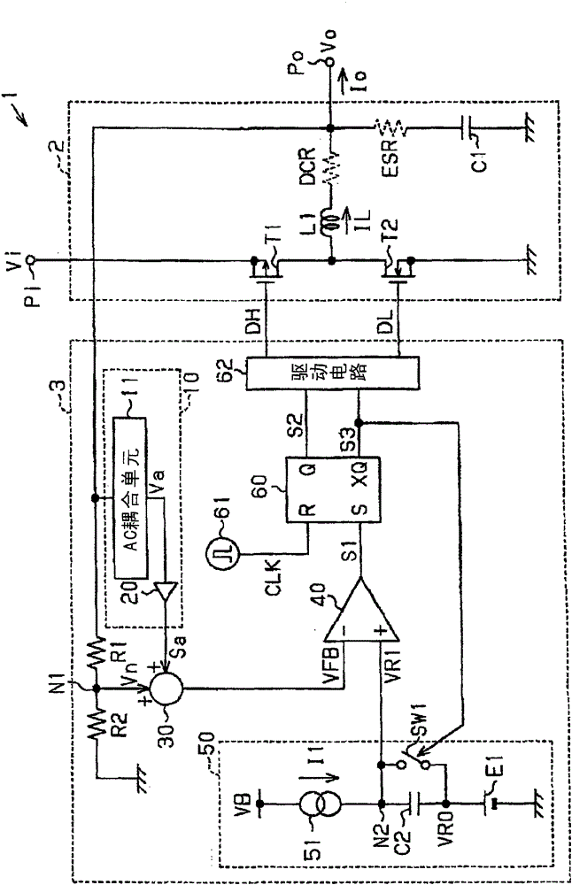
[0028] Such as figure 1 As shown, the DC-DC converter 1 includes a converter unit 2 and a control circuit 3 for controlling the converter unit 2 . The converter unit 2 generates an output voltage Vo which is lower than the input voltage Vi.

[0029] An example of the internal structure of the converter unit 2 is described below.

[0030] The input voltage Vi is supplied to the input terminal Pi. The transistor T1 and the transistor T2 are connected in series between the input terminal Pi and a power supply line (in this case, a ground point) whose potential is lower than that of the input voltage Vi. exist figure 1 Among them, the transistor T1 may also be called a main transistor, and the transistor T2 may be called a synchronous transistor. Transistor T1 is a P-channel MOS transistor, and transistor T2 is an N-channel MOS transistor.

[0031] The transistor T1 has a first terminal (source) connec...


PUM


Abstract

A control circuit of a power supply that generates an output voltage from an input voltage includes a gain adjustment circuit that adjusts a gain of an alternating-current component of the output voltage. An addition circuit adds an output signal of the gain adjustment circuit to a first feedback voltage, which is in accordance with the output voltage, to generate a second feedback voltage. A voltage generation circuit generates a comparison reference voltage that changes at a given rate with respect to a first reference voltage that is set according to a target value of the output voltage. A switch control circuit controls the output voltage by switching a switch circuit, to which the input voltage is supplied, at a timing according to a result of a comparison of the second feedback voltage with the comparison reference voltage.

Description

technical field [0001] The present disclosure relates to a control circuit, a power supply device, and a method of controlling a power supply. Background technique [0002] In electronic devices, switching power supplies are used to supply power to loads. For example, a DC-DC converter that converts a DC voltage to a different DC voltage is used. Japanese Laid-Open Patent No. 2010-051073 describes a comparator-type DC-DC converter that can respond to sudden changes in load at high speed. [0003] Figure 14 An example of a comparator-type DC-DC converter 4 according to the prior art is shown. The DC-DC converter 4 includes a converter unit 5 and a control circuit 6 . Converter unit 5 includes transistors T11 and T12, coil L11, and capacitor C11. [0004] The comparator 80 provided in the control circuit 6 receives the feedback voltage VFB1 and the reference voltage VR11, and the feedback voltage VFB1 is generated according to the output voltage Vo1. exist Figure 14 , t...

Claims


Application Information

Patent Timeline
Patent Type & Authority Patents(China)
IPC IPC(8): H02M3/157H02M1/38
CPCH02M3/1563
Inventor 矢铺诚
Owner SOCIONEXT INC
Why Eureka
Try Eureka