Control device of power factor correcting circuit and control method

A power factor correction and control device technology, which is applied to control/regulating systems, regulating electrical variables, instruments, etc., can solve the problems of difficult control loops, decreased inductance values, and increased current loop bandwidth of the power factor correction circuit 200. The effect of high gain, wide gain bandwidth

Active Publication Date: 2013-08-21
VERTIV CORP
View PDF0 Cites 0 Cited by
  • Summary
  • Abstract
  • Description
  • Claims
  • Application Information

AI Technical Summary

Problems solved by technology

Moreover, since the current loop bandwidth of the power factor correction circuit 200 is inversely proportional to the inductance value of the inductance of the power factor correction circuit 200, as the output load increases, the DC magnetizing force will increase, resulting in an inductance of the inductance of the power factor correction circuit 200 value decreases, so that the current loop bandwidth of the power factor correction circuit 200 increases continuously
Generally speaking, in the actual application of communication power supply products, when the output is continuously loaded from no load to full load, the inductance value of the inductor of the power factor correction circuit 200 will usually drop significantly, and the current loop bandwidth of the power factor correction circuit 200 will change. It makes it difficult for the control loop to meet the phase margin and gain margin requirements in the full load range

Method used


Image

  • Control device of power factor correcting circuit and control method
  • Control device of power factor correcting circuit and control method
  • Control device of power factor correcting circuit and control method

Examples


Embodiment Construction

[0037] The present invention will be further described below in conjunction with the accompanying drawings and preferred embodiments.

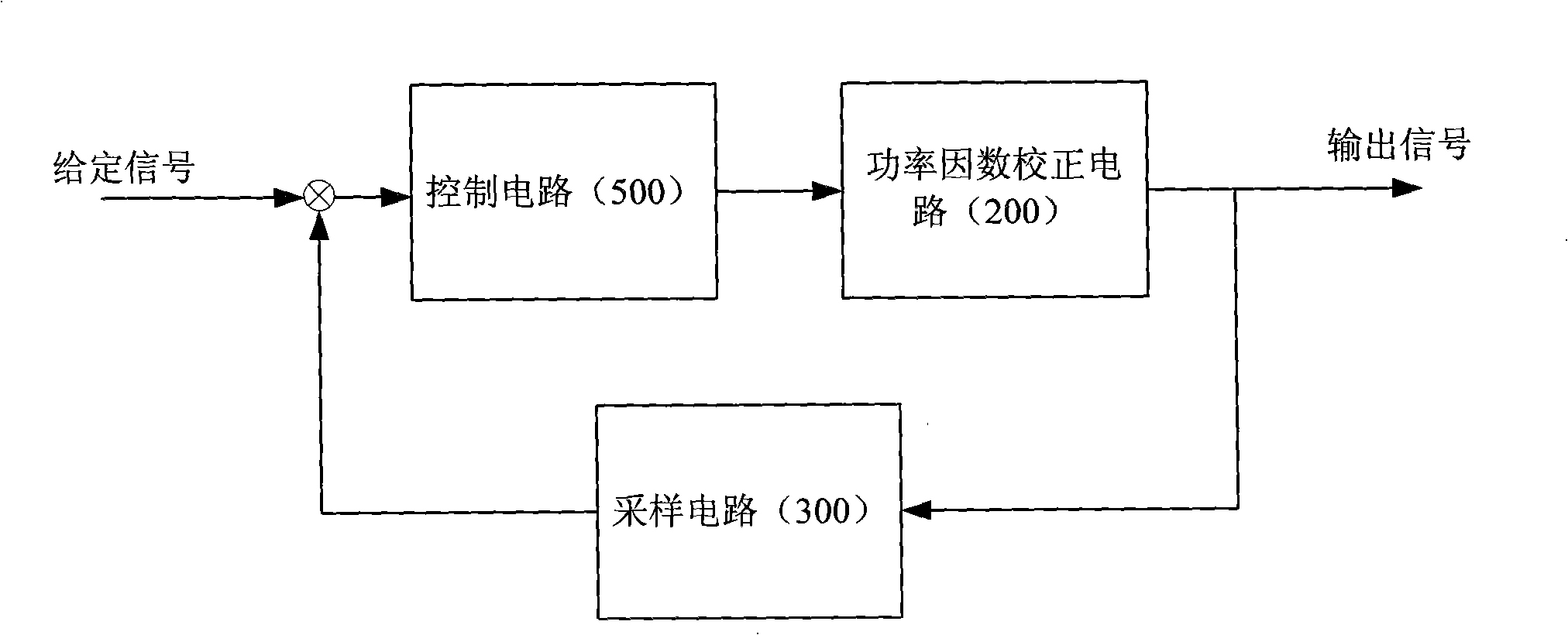
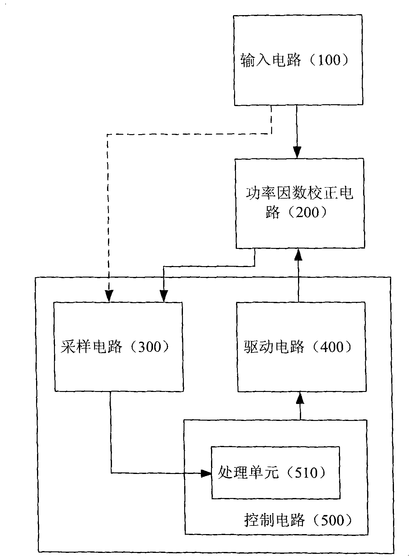
[0038] Such as figure 2 As shown, the power factor correction circuit 200 is a power conversion circuit driven by the double half-wave DC input from the input circuit 100 . The control device of the power factor correction circuit 200 includes: a sampling circuit 300 , a driving circuit 400 and a control circuit 500 .

[0039] Wherein, the control circuit 500 includes: a processing unit 510; the sampling circuit 300 collects the state signal of the power factor correction circuit 200 and sends it to the processing unit 510; the processing unit 510 controls the state signal according to the state signal The output parameter of the control circuit 500 is used to control the driving circuit 400; the driving circuit 400 outputs a corresponding driving signal to control the power factor correction circuit 200.

[0040] Of course, the sampling ci...


PUM


Abstract

The invention provides a control device of a power factor correcting circuit and a control method. The power factor correcting circuit (200) is driven by the input of an input circuit (100), the control device comprises a sampling circuit (300), a driving circuit (400) and a control circuit (500), wherein the control circuit (500) comprises a processing unit (510), the sampling circuit (300) acquires the status signal of the power factor correcting circuit (200), and sends the signal to the processing unit (510), the processing unit (510) controls the output parameters of the control circuit (500) according to the status signal so as to control the driving circuit (400), and the driving circuit (400) outputs corresponding driving signals so as to control the power factor correcting circuit (200). The invention has the advantage that the control has sufficient phase margin, wide gain bandwidth and high gain.

Description

technical field [0001] The invention relates to a control device and a control method of a power factor correction circuit. Background technique [0002] The structure of the current automated electrical system such as figure 1 As shown, the circuit performing the corresponding function is the power factor correction circuit 200, and its output signal is fed back to the control circuit 500 through the sampling circuit 300 to correct its power factor (PF) and obtain the desired output. [0003] In the field of communication power supply products, the power factor correction circuit 200 is the main power circuit, and most of the inductor cores used in it are iron powder cores, sendust, amorphous materials, ferrite, etc. [0004] The control circuit 500 of the communication power supply product usually implements traditional PI control through analog or digital control. The traditional PI control method has the advantages of simple implementation and convenient parameter sett...

Claims


Application Information

Patent Timeline
Patent Type & Authority Patents(China)
IPC IPC(8): G05F1/70
Inventor 顾军李剑吕有根
Owner VERTIV CORP
Why Eureka
Try Eureka