Supercharge Your Innovation With Domain-Expert AI Agents!

isolator unit

A technology of isolators and isolation layers, applied in the direction of laminated components, heat exchanger types, indirect heat exchangers, etc., which can solve the problems of reduced performance and reusability, failure to maintain good sealing of pressure distribution, etc.

Inactive Publication Date: 2016-09-28
ALFA LAVAL CORP AB
View PDF9 Cites 0 Cited by
  • Summary
  • Abstract
  • Description
  • Claims
  • Application Information

AI Technical Summary

Problems solved by technology

After being subjected to sharp temperature gradients, such as during rapid heating or cooling of flow plates, such end plates can deform and thus fail to maintain a uniform pressure distribution and thus a good seal in the stack of plates
[0003] Separator plates manufactured from polymeric materials with suitable insulating properties, such as PTFE (polytetrafluoroethylene), suffer from the disadvantage that they can deform plastically under high pressure and high temperature, resulting in reduced performance and reusability

Method used


Image

  • isolator unit
  • isolator unit

Examples


Embodiment Construction

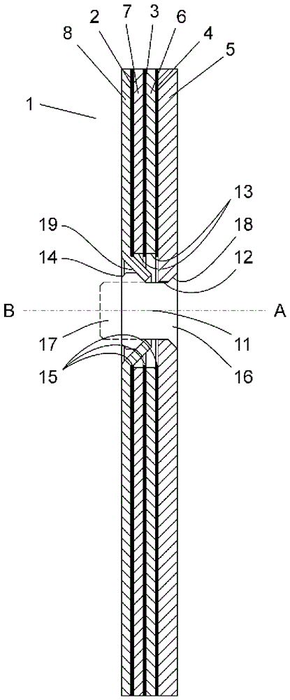
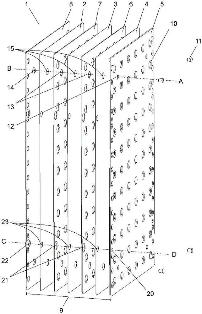
[0026] The isolator unit 1 is shown in exploded view in figure 1 is shown in , where three isolation layers 2 , 3 and 4 are positioned in the middle of four plates 5 , 6 , 7 and 8 . The insulating layers and plates form a sandwich structure 9 . The isolation layer is made of expanded PTFE (expanded polytetrafluoroethylene) having a thickness of 1 mm in the uncompressed state. Plates 5, 6, 7 and 8 are metal plates made of acid-resistant stainless steel. The plate 5 defining one of the outer sides of the sandwich structure 9 has a thickness of 2 mm. Plates 6 and 7, and plate 8, which defines the other outer side of the sandwich structure, are 1 mm thick. The transverse dimension of the spacer unit is greater than 100mm, preferably in the range 200-600mm, but possibly greater than 1000mm.

[0027] Each of the plates 5, 6 and 7 is provided with a patterned surface on both sides of the plate by means of a plurality of holes 10 distributed over each plate. The holes occupy appr...


PUM


Abstract

The invention relates to an insulator unit for a multipurpose flow module, such as a plate reactor, comprising a plurality of thermally insulating layers arranged in a sandwich structure with a plurality of plates, to provide thermal insulation across the sandwich structure. The invention further relates to the use of such an insulator unit in a multipurpose flow module comprising one or more flow plates, to thermally insulate parts of the multipurpose flow module from each other.

Description

technical field [0001] The present invention relates to isolator units for multipurpose flow modules, such as continuous plate reactors, and the use of such isolator units in multipurpose flow modules. Background technique [0002] In continuous plate reactors or flow modules for other purposes, stacks of two or more flow plates are clamped together with optional heat exchanger plates, baffle plates and / or end plates to form a or multiple flow channels. The plates are clamped together under high pressure in order to ensure a good seal of the flow channels. Different parts of the reactor may need to be thermally isolated from adjacent parts of the reactor to reduce problems related to heat transfer. Adjacent flow channels may need to be isolated from each other in order to minimize any thermal crosstalk between reaction channels. The end plates of the reactor may need to be thermally isolated from the rest of the stack of plates in order to maintain a good seal of the flow...

Claims


Application Information

Patent Timeline
Patent Type & Authority Patents(China)
IPC IPC(8): B01J19/24F28D9/00F28F3/08
CPCB01J19/249B01J2219/2453B01J2219/2458B01J2219/246B01J2219/2461B01J2219/2486B01J2219/249B01J2219/2493B01J2219/2497F28F3/086
Inventor K.赫格伦M.林格瓦尔
Owner ALFA LAVAL CORP AB
Features
  • R&D
  • Intellectual Property
  • Life Sciences
  • Materials
  • Tech Scout
  • Unparalleled Data Quality
  • Higher Quality Content
  • 60% Fewer Hallucinations
Learn More