Thermally insulated pot

a technology of thermal insulation and pots, which is applied in the field of thermal insulation pots, can solve the problems of high manufacturing cost, insufficient sealing of thermal insulation cooking devices, and heavy lifting of pots with sealed insulation cavities

Inactive Publication Date: 2006-08-08
PATERSONS ENTERPRISES
View PDF13 Cites 96 Cited by
  • Summary
  • Abstract
  • Description
  • Claims
  • Application Information

AI Technical Summary

Benefits of technology

[0012]Another object of the present invention is to provide a tightly sealed insulation cavity that provides excellent thermal insulation.
[0013]A further object of the present invention is to provide a cooking pot with thermal insulation that can conveniently function as a conventional cooking pot.

Problems solved by technology

Having the cavity sealed is a costly process, leading to high manufacturing costs.
In addition, pots with sealed insulation cavities are heavy to lift.
Thermally insulated cooking devices without properly sealed insulation cavities, however, would not provide enough thermal insulation, and are therefore impractical.

Method used


Image

  • Thermally insulated pot
  • Thermally insulated pot
  • Thermally insulated pot

Examples


Embodiment Construction

FIGS. 1-9—Preferred Embodiment

[0034]Before explaining the disclosed embodiments of the present invention in detail it is to be understood that the invention is not limited in its application to the details of the particular arrangement shown since the invention is capable of other embodiments. Also, the terminology used herein is for the purpose of description and not of limitation.

[0035]Reference will now be made in detail to the preferred embodiments of the present invention, examples of which are illustrated in the accompanying drawings.

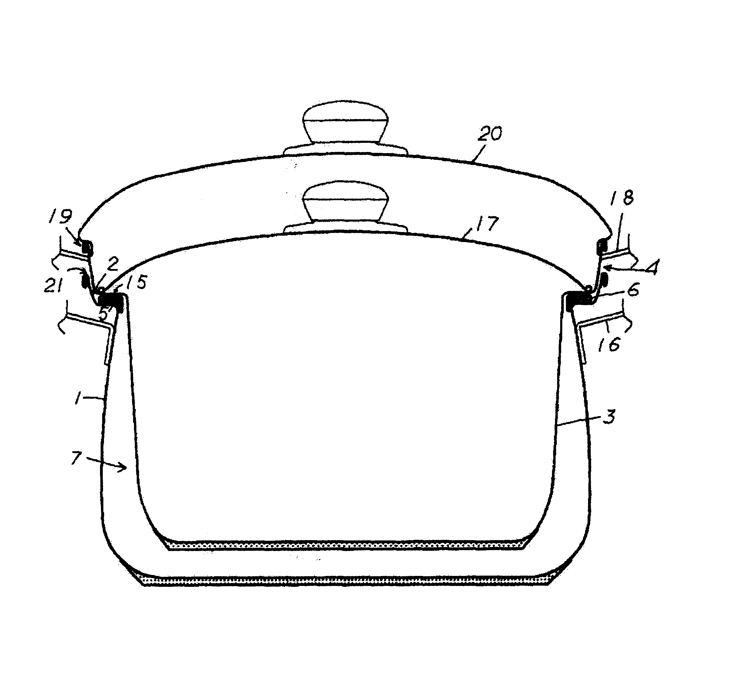
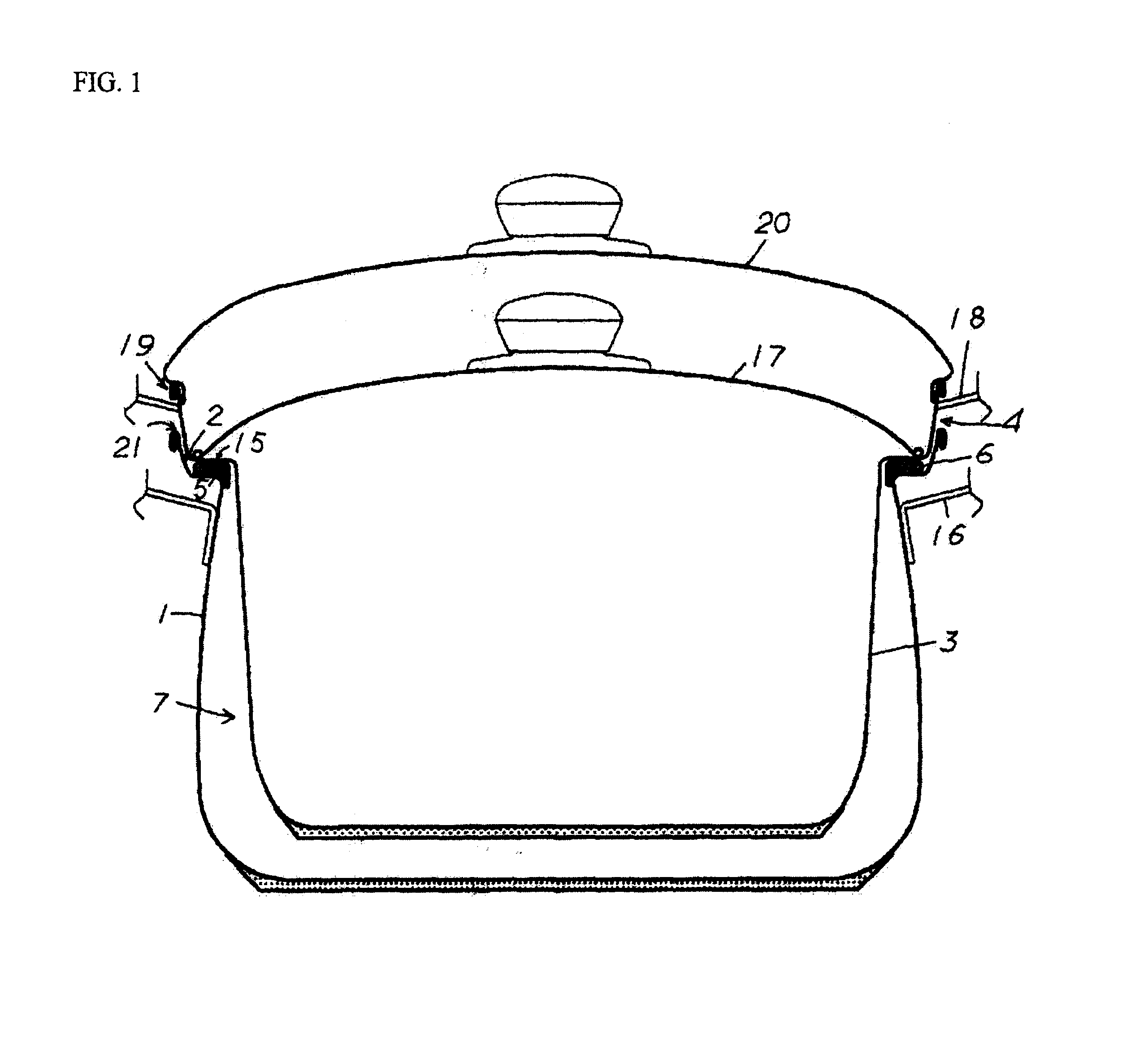
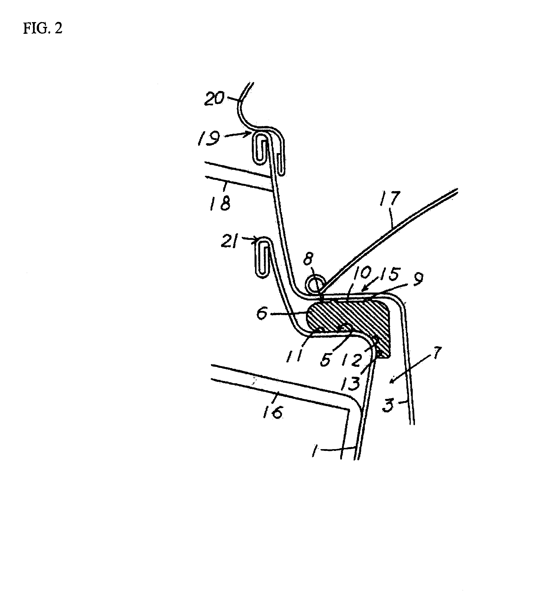
[0036]A cooking apparatus according to a preferred embodiment of the present invention is illustrated in FIGS. 1 to 9. In FIG. 1 an inner pot 3 is suspended within an outer pot 1. The outer pot's 1 inner top circumferential area 2 has a step area 5, where a packing ring 6 is positioned. The packing ring 6, made of a pliable material, supports the inner pot 3 by having a top outer circumferential area 4 of the inner pot 3 hang within the outer pot ...


PUM


Abstract

A thermally insulated cooking pot consists of an outer pot and an inner pot. The inner pot is suspended within the outer pot by hanging from the top inner circumferential area of the outer pot with its own top outer circumferential area. The space between the inner and outer pots becomes an insulation cavity. The contact point between the two pots is sealed by a pliable packing ring with an L-shaped cross-section, thereby sealing the insulation cavity. This sealed insulation cavity provides excellent thermal insulation. The packing ring contains a plurality of protrusions on the surface that come into contact with the inner pot to prevent the packing ring from sticking to the inner pot. The gap formed between the packing ring protrusions and the inner pot prevents the inner pot from sticking to the packing ring.

Description

CROSS-REFERENCE TO RELATED APPLICATIONS[0001]Country: Japan[0002]Application Reference Number: 2000-142987[0003]Filing Date: May 14, 2001FEDERALLY SPONSORED RESEARCH[0004]Not ApplicableSEQUENCE LISTING OR PROGRAM[0005]Not ApplicableBACKGROUND[0006]1. Field of Invention[0007]This invention relates to cooking devices, and particularly, to a thermally insulated pot.[0008]2. Description of Prior Art[0009]Existing thermally insulated cooking devices are double structured, with a sealed insulation cavity between the inner and outer vessels. Having the cavity sealed is a costly process, leading to high manufacturing costs. In addition, pots with sealed insulation cavities are heavy to lift.[0010]Thermally insulated cooking devices without properly sealed insulation cavities, however, would not provide enough thermal insulation, and are therefore impractical. The present invention discovered this.BRIEF SUMMARY OF THE INVENTION[0011]It is therefore an object of the present invention to addre...

Claims


Application Information

Patent Timeline
Patent Type & Authority Patents(United States)
IPC IPC(8): A47J37/12A23L1/00A47J27/00A47J27/06A47J27/08A47J27/10A47J27/13A47J36/36A47J41/00
CPCA47J36/36A47J41/0077Y10S220/912A47J27/13
Inventor YOKOYAMA, KATSUNORI
Owner PATERSONS ENTERPRISES
Why Eureka
Try Eureka