
Magnetic retaining device for false tooth connecting rod

A connecting rod and magnetic technology, applied in the direction of fasteners, etc., can solve the problems of increased cost, patient pain, inconvenience, etc., and achieve the effects of easy cleaning, convenient use, and reduced foreign body sensation

Inactive Publication Date: 2013-03-13
陆金泉
View PDF9 Cites 2 Cited by
  • Summary
  • Abstract
  • Description
  • Claims
  • Application Information

AI Technical Summary

Problems solved by technology

The disadvantages of the existing technology are: the root of the abutment tooth is required to be long and thick, and the central post core is long. If the root of the residual tooth is short, thin and loose, it cannot be fixed firmly and is easy to fall off. It needs to be bonded and fixed repeatedly, causing pain for the patient. Increased cost, extremely inconvenient

Method used


Image

  • Magnetic retaining device for false tooth connecting rod
  • Magnetic retaining device for false tooth connecting rod
  • Magnetic retaining device for false tooth connecting rod

Examples


Embodiment 1

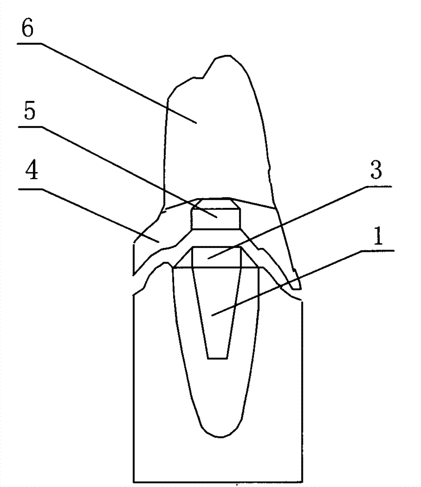
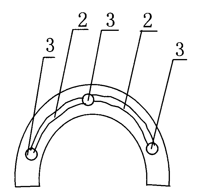
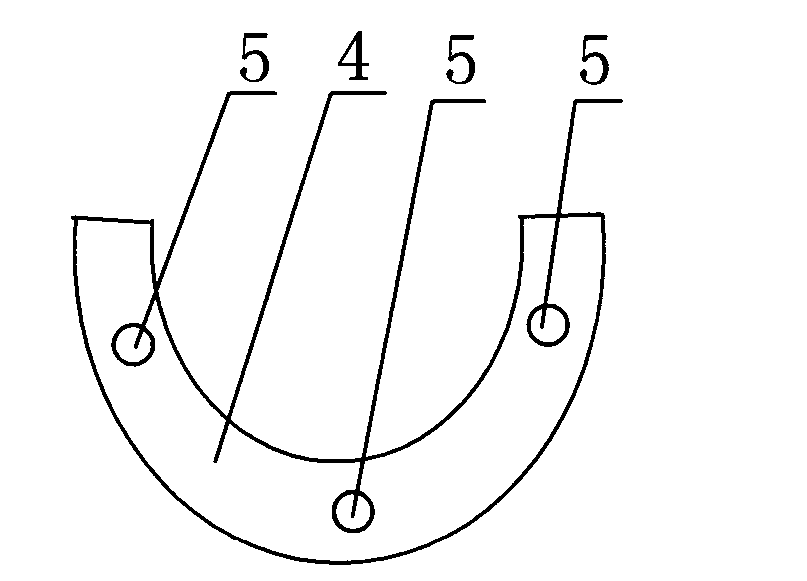
[0025] Ms. Cai, aged 76, had 3 residual teeth and crowns in the upper jaw, distributed in the left, middle and right. Drill holes in the centers of the three residual teeth and crowns, and glue the three metal central posts 1 into the holes respectively. The upper part of the central post 1 is connected with a magnetic armature 3. The metal connecting rod 2 is cast, and the metal The connecting rod 2 and the magnetic armature 3 are welded together, so that 3 residual teeth and residual crowns; 3 metal center posts 1; and 3 magnetic armatures 3 are connected as a whole, such as figure 2 shown. Dentures 6 are set on the top of the metal base plate 4; three magnets 5 are set on the bottom of the metal base plate 4, and the positions of the three magnets 5 correspond to the three magnetic armatures 3 on the metal connecting rod 2 respectively, as image 3 shown. When in use, the patient places the metal base plate 4 and the denture 6 connected to the metal base plate 4 in the o...

Embodiment 2

[0027] Mr. Li, aged 65, has 4 residual teeth and crowns in the upper jaw, which are distributed in different positions on the left, middle and right. During the implementation of the present invention, holes are punched at the centers of 4 residual teeth and residual crowns, and 4 metal central posts 1 are respectively bonded in the holes with glue, and the top of the central post 1 is connected with a magnetic armature 3 . The metal connecting rod 2 is cast, and the metal connecting rod 2 welds the magnetic armature 3 together, so that 4 residual teeth and residual crowns; 4 metal center posts 1; and 4 magnetic armatures 3 are connected as a whole. A denture 6 is set on the top of the metal base plate 4; four magnets 5 are set on the bottom of the metal base plate 4, and the positions of the four magnets 5 correspond to the four magnetic armatures 3 on the metal connecting rod 2 respectively. During use, the patient places the metal base plate 4 and the denture 6 connected to...

Embodiment 3

[0029] Ms. Wang, aged 51, has 2 residual teeth and crowns in the mandible, which are distributed in different positions on the left and right. During the implementation of the present invention, holes are punched at the centers of 2 residual teeth and residual crowns, and 2 metal central posts 1 are respectively bonded in the holes with glue, and the top of the central post 1 is connected with a magnetic armature 3 . The metal connecting rod 2 is cast, and the metal connecting rod 2 welds the magnetic armature 3 together, so that 2 residual teeth, residual crowns, 2 metal center posts 1, and 2 magnetic armatures 3 are connected as a whole. A denture 6 is set on the top of the metal base plate 4; two magnets 5 are set on the bottom of the metal base plate 4, and the positions of the two magnets 5 correspond to the two magnetic armatures 3 on the metal connecting rod 2 respectively. During use, the patient places the metal base plate 4 and the denture 6 connected to the metal ba...


PUM


Abstract

The invention belongs to the magnetic retaining technology of an oral false tooth, and in particular relates to a magnetic retaining device for a false tooth connecting rod. In the prior art, a magnetic armature is fixedly arranged on a tooth or a single root of a residual root and a residual crown, so that the central post cores are not connected with each other. The defects are that for the abutment, the root of the tooth needs to be long and thick and the central post core needs to be long, and the false tooth is easy to fall. According to the magnetic retaining device for the false tooth connecting rod provided by the invention, metal central posts (1) are bonded on the residual root of the abutment and connected together through a metal connecting rod (2); 2-4 magnetic armatures (3) are arranged on the metal connecting rod (2); the false tooth (6) is arranged on a basic layer board (4); and 2-4 magnets (5) are arranged in positions of the lower part of the basic layer board (4) corresponding to the magnetic armatures (3) on the metal connecting rod (2). The magnetic retaining device for the false tooth connecting rod provided by the invention has the advantages that the requirement on the abutment is low, and the false tooth can be firmly fixed even if the root is short and loose; the false tooth is stable to retain, and the central post core is not easy to fall, so that the service life is prolonged; and the magnetic retaining device for the false tooth connecting rod is simple to pick and wear, easy to clean, and convenient and comfortable for patients to use.

Description

technical field [0001] The invention belongs to the magnetic retention technology of oral dentures, in particular to a magnetic retention device for denture connecting rods. Background technique [0002] Oral denture magnetic retention technology is to use the magnetic principle to set a magnetic armature on the residual root and crown of the abutment tooth, and set a magnet on the base plate of the denture. The armature and the magnet attract each other, so as to realize the fixation of the denture in the oral cavity. The denture magnetic retention technology does not require the use of metal clasps. It has the advantages of avoiding the damage of the clasps to the abutment teeth, firm denture fixation, simple removal and wearing, easy to clean, and beautiful oral cavity. It is the latest technology in oral medicine. The inventor has been studying oral denture fixation technology for a long time, and once had patent projects such as ZL00216437X; ZL002166992; ZL002170523; ZL...

Claims


Application Information

Patent Timeline
Patent Type & Authority Applications(China)
IPC IPC(8): A61C13/235
Inventor 陆金泉
Owner 陆金泉
Learn More