Punching head

A punch and necking technology, which is applied in the field of pipe end forming and processing molds, can solve the problems of flanging, low production efficiency, complicated procedures, etc., and achieve the effects of ensuring the inner diameter size, improving production efficiency, and simple production procedures.

Active Publication Date: 2013-03-13
GREE ELECTRIC APPLIANCES INC OF ZHUHAI
View PDF5 Cites 11 Cited by
  • Summary
  • Abstract
  • Description
  • Claims
  • Application Information

AI Technical Summary

Problems solved by technology

Therefore, the deburring process needs to be processed in two strokes. Generally, the shrinking die operation is performed first and then the expanding die operation is performed. Since the two processes cannot be carried out at the same

Method used


Image

  • Punching head
  • Punching head

Examples


Example Embodiment

[0019] It should be noted that the embodiments in the application and the features in the embodiments can be combined with each other if there is no conflict. Hereinafter, the present invention will be described in detail with reference to the drawings and in conjunction with the embodiments.

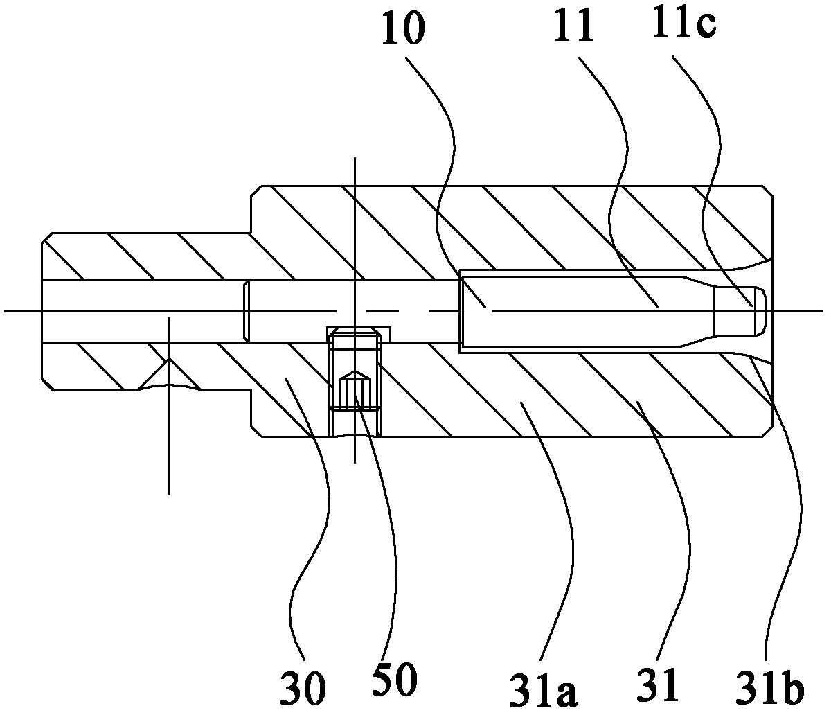
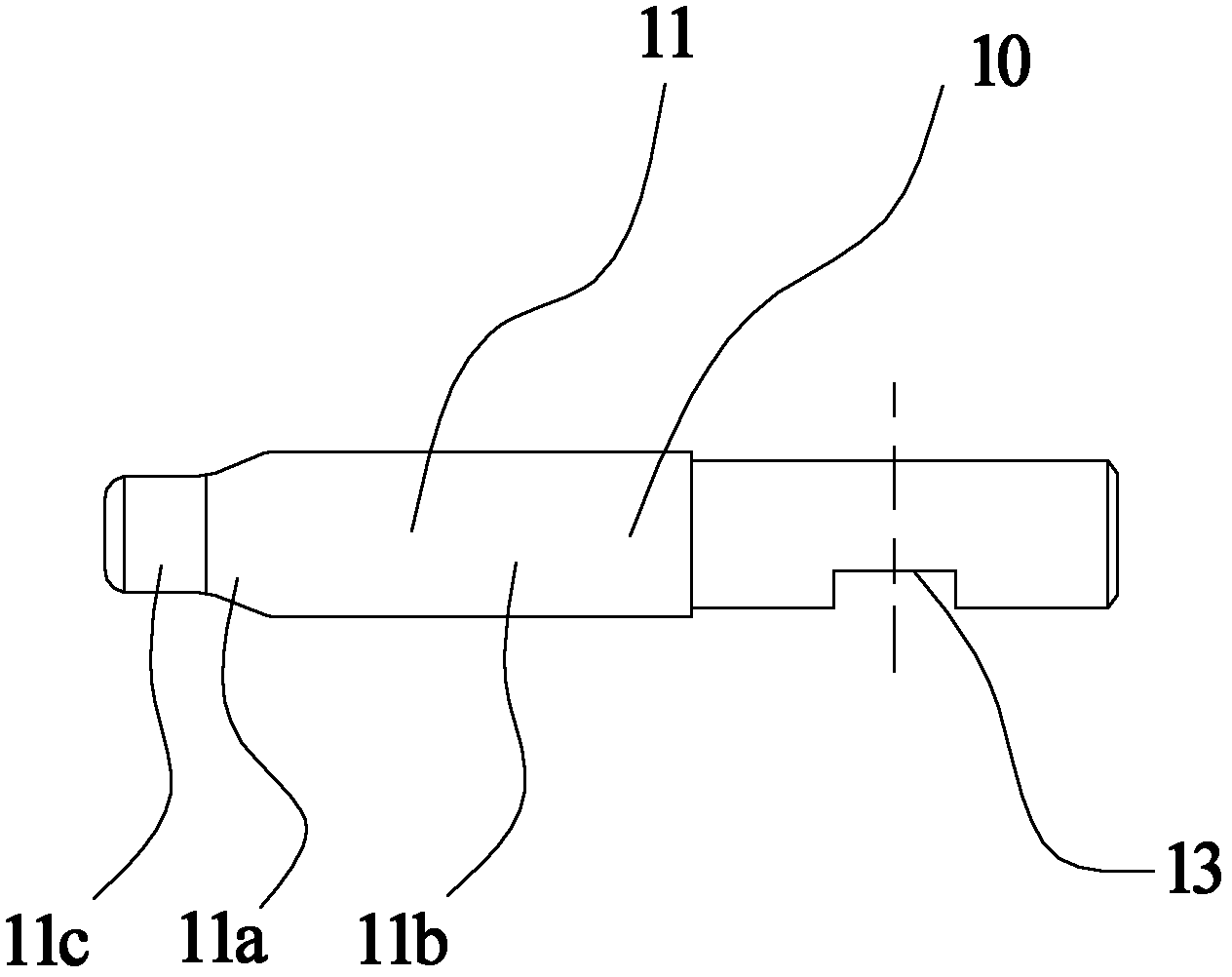
[0020] figure 1 A schematic cross-sectional view of an embodiment of the punch according to the present invention is shown. Such as figure 1 As shown, it can be seen from the figure that the punch of this embodiment includes: a flaring core 10 and a necking jacket 30. The first end of the flaring core 10 is the flaring end 11, and the second end of the flaring core 10 is the connecting end; the flaring core 10 is installed in the inner hole of the necking jacket 30, and the first end of the necking jacket 30 is One end is a necked end 31, and there is a gap between the necked end 31 and the flared end 11.

[0021] The punch of this embodiment is especially used for the deburring process of...


PUM


Abstract

The invention provides a punching head, which comprises an expanding mold core (10) and a reducing jacket (30), wherein the first end of the expanding mold core (10) is an expanding end (11) and the second end of the expanding mold core (10) is a connecting end; and the expanding mold core (10) is installed in the inner hole of the reducing jacket (30), the first end of the reducing jacket (30) is a reducing end (31), and a gap is kept between the reducing end (31) and the expanding end (11). The punching head has the advantages of high production accuracy, simple production process and high efficiency.

Description

technical field [0001] The invention relates to the field of pipe end forming processing dies, in particular to a punch. Background technique [0002] The nozzle quality of copper pipe deburring has always been a bottleneck in the pipe end forming process. The quality of processing directly affects the efficiency of inner piping and upper quick connectors, and even causes the shutdown of final assembly and helium inspection. Since the current pipe end forming dies only have two kinds of common flaring dies and shrinking dies, and there is no special deburring punch, it is generally selected according to the existing flanging dies when removing internal burrs, and shrinking dies are used when removing external burrs. Die. [0003] In order to ensure the quality requirements of helium inspection and final assembly of quick connectors and internal piping, it is often necessary to deal with internal burrs and external flanging problems at the same time to ensure the size requir...

Claims


Application Information

Patent Timeline
IPC IPC(8): B21D37/00B21D41/00
Inventor 曾霄林祥龙王仁聪
Owner GREE ELECTRIC APPLIANCES INC OF ZHUHAI
Why Eureka
Try Eureka