Push plate demoulding mechanism

A demoulding mechanism and push plate technology, applied in the field of push plate demoulding mechanism, can solve problems such as uneven demoulding, uneven thrust, and easy deformation of rubber parts

Inactive Publication Date: 2013-03-13
DALIAN GAOHONG PRECISION MOLD
View PDF0 Cites 1 Cited by
  • Summary
  • Abstract
  • Description
  • Claims
  • Application Information

AI Technical Summary

Problems solved by technology

[0002] In the prior art, the ejection mechanism of the push plate has uneven thrust force due to the plastic part with thimble traces and the small multi-cavity shell, and the demoulding is not stable, and the plastic part is easily deformed

Method used


Image

  • Push plate demoulding mechanism

Examples


Embodiment Construction

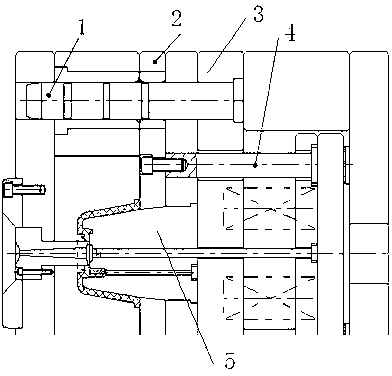
[0011] Such as figure 1 As shown, the push plate demoulding mechanism includes side nail 1, push plate 2, fixed plate 3, return needle 4 and core 5, push plate 2 is connected with fixed plate 3, return needle 4, side nail 1 and push plate 2 It is connected with the fixed plate 3, the push plate 2 and the return needle 4 are connected by screws, and the matching structure between the push plate and the core should be a conical surface; this can reduce movement scratches and play an auxiliary guiding role; the inclination of the conical surface should be 3~10°, the inner hole of the push plate should be 0.2~0.3mm larger than the core forming part (one side). The wire cutting process causes the core to overcut, and the push plate and the back needle are connected by screws. After the push plate is demoulded, it must be ensured that the plastic parts do not stay on the push plate.


PUM


Abstract

The invention discloses a push plate demoulding mechanism, which includes an edge nail (1), a push plate (2), a fixation plate (3), a back stitch (4) and a mold core (5). The push plate (2) is in connection with the fixation plate (3) and the back stitch (4), and the edge nail (1) is in connection with the push plate (2) and the fixation plate (3). The push plate demoulding mechanism provided in the invention is suitable for rubber pieces that have a deep cylinder shape, a thin wall and does not allow an ejector pin mark, or is suitable for a small shell with multiple cavities (such as a button rubber piece). The push plate demoulding mechanism has the characteristics of uniform thrust, smooth demoulding, and difficult deformation of rubber pieces.

Description

technical field [0001] The invention relates to a push plate demoulding mechanism. Background technique [0002] In the prior art, due to the plastic parts with thimble traces and the small multi-cavity shell of the push plate demoulding mechanism, the thrust force of the structure is uneven, the demoulding is not stable, and the plastic parts are easily deformed. Contents of the invention [0003] The purpose of the present invention is to provide a push plate demoulding mechanism. [0004] The technical solution adopted by the present invention to achieve the above purpose is: a push plate demoulding mechanism, including side nails (1), push plate (2), fixed plate (3), return needle (4) and core (5 ), the push plate (2) is connected with the fixed plate (3) and the return needle (4), and the side nail (1) is connected with the push plate (2) and the fixed plate (3). [0005] The push plate (2) is connected with the back needle (4) by screws. [0006] The matching stru...

Claims


Application Information

Patent Timeline
Patent Type & Authority Applications(China)
IPC IPC(8): B29C33/44
Inventor 车向前
Owner DALIAN GAOHONG PRECISION MOLD
Why Eureka
Try Eureka