Vehicle strut tower support reinforcing structure

A technology for strengthening structures and struts, which is applied to superstructures, vehicle parts, superstructure subassemblies, etc., can solve problems such as increased cost and weight, and increased number of parts, so as to improve bending rigidity and compression rigidity, and prevent relative Displacement, the effect of securing the steering stability

Active Publication Date: 2013-03-13
MITSUBISHI MOTORS CORP
View PDF6 Cites 9 Cited by
  • Summary
  • Abstract
  • Description
  • Claims
  • Application Information

AI Technical Summary

Problems solved by technology

[0008] However, as in the vehicle strut tower support rod of Japanese Patent Document 1, when the structure in which the upper ends of the left and right strut tower supports are connected by the strut tower support rod, although the rigidity of the vehicle body is improved, the , the number of parts increases, and installation space needs to be secured, and it also leads to an increase in cost and weight

Method used


Image

  • Vehicle strut tower support reinforcing structure
  • Vehicle strut tower support reinforcing structure
  • Vehicle strut tower support reinforcing structure

Examples


Embodiment Construction

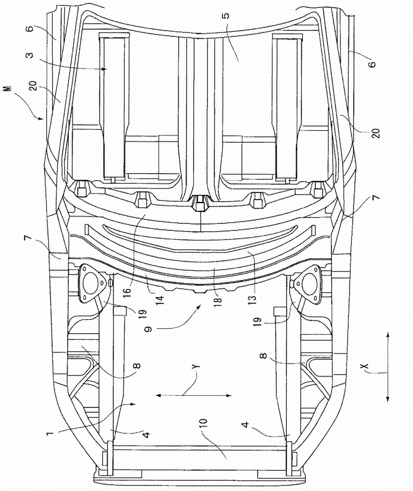
[0031] Refer to the following figure 1 The vehicle front body M to which the vehicle strut tower support reinforcement structure according to the first embodiment of the present invention is applied will be described. An engine compartment 1 is arranged at the front of the vehicle, and a vehicle compartment 3 is formed behind the engine compartment 1 with an instrument panel 2 interposed therebetween. On both left and right ends of the engine compartment 1 , long side beams 4 are arranged side by side along the front-rear direction X, and the rear ends of the two side beams 4 are welded to the lower rear bent portion of the instrument panel 2 from below. Furthermore, the front end sides of the two side members 4 are welded to each other at a front-end cross member (not shown), thereby securing the front rigidity of the engine room. A front portion of a floor 5 is integrally joined to a rear end edge of a lower curved portion of the instrument panel 2 . The left and right si...


PUM


Abstract

The structure has a cowl top (9) including lower wall portion (13) that is joined to upper portion of the dash panel for dividing engine compartment (1). The cowl top is bent from a front wall portion, and is formed in lower end of vacant room. A strut tower is formed along right-and left sides of inner wall of engine compartment of vehicle. A connection bracket is formed by welding flange of side wall of the housing portion and front-wall portion of cowl top. A bead (18) is formed in an area without interruption, and is configured to tie position facing right and left strut tower.

Description

technical field [0001] The present invention relates to a vehicle strut tower reinforcement structure for controlling relative displacement of left and right strut towers arranged to protrude from left and right inner walls of a vehicle engine room. Background technique [0002] Front suspensions (Front Suspension) that interfere with the ground reaction force from the wheels and support the wheels steerably are installed on the left and right sides of the front of the vehicle body. The upper parts of the left and right struts used in the front suspension are supported by a pair of substantially cylindrical strut towers protruding from the inner walls of the engine room on both sides in the vehicle width direction. The sliding column tower bearing needs to overcome the load acting on the suspension during driving, position the support strut, and ensure the handling stability, and, in order to achieve this effect, the sliding column tower bearing needs to have sufficient rigi...

Claims


Application Information

Patent Timeline
Patent Type & Authority Applications(China)
IPC IPC(8): B62D25/08
Inventor 生稻由纪子竹内秀纪
Owner MITSUBISHI MOTORS CORP
Why Eureka
Try Eureka