Vehicle-body structure of vehicle and manufacturing method of the same

A body and vehicle technology, which is applied to the vehicle body structure and its manufacturing field, can solve the problems that the vehicle cannot be effectively restrained, and achieve the effects of improving rigidity, avoiding the increase of body weight, and suppressing deformation

A body and vehicle technology, which is applied to the vehicle body structure and its manufacturing field, can solve the problems that the vehicle cannot be effectively restrained, and achieve the effects of improving rigidity, avoiding the increase of body weight, and suppressing deformation

CN102963437AActive Publication Date: 2013-03-13MAZDA MOTOR CORP

Image

  • Vehicle-body structure of vehicle and manufacturing method of the same
  • Vehicle-body structure of vehicle and manufacturing method of the same
  • Vehicle-body structure of vehicle and manufacturing method of the same

Examples


Embodiment Construction

[0039] Hereinafter, specific embodiments of the present invention will be described with reference to the drawings.

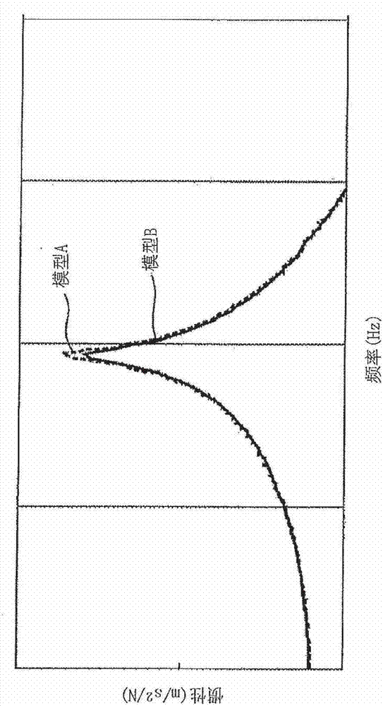
[0040] Before explaining the specific structure in which the present invention is applied to an actual vehicle body, first, the results of a simulation performed on a model with a simplified structure will be described.

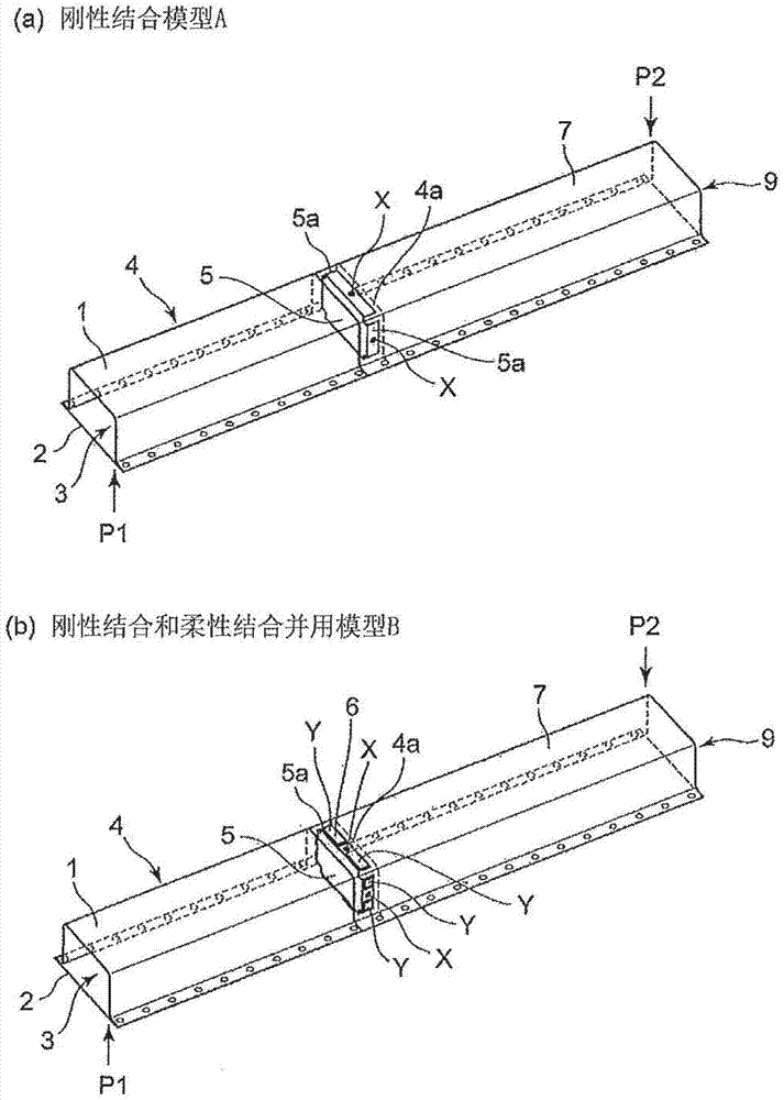
[0041] figure 1 (a) represents the rigid binding model A used for this simulation, figure 1 (b) represents the combination of rigid bonding and flexible bonding Model B. Such as figure 1 As shown in (a) and (b), in any model of rigid bonded model A and rigid bonded and flexible bonded model B, the first part 1, the third part 7, and the plate-shaped cap-shaped section are used. The second member 2 is used as a vehicle body structural member, and the hollow frame 4 extending in the longitudinal direction is formed by joining the second member 2 on one surface of the first member 1 and the third member 7 .

[0042] Both the first member 1 and ...


PUM


Abstract

In a vehicle-body structure of a vehicle which comprises vehicle-body forming members forming a closed-section portion and having a dent portion which dents toward an inside of the closed-section portion, and a reinforcing member provided in the closed-section portion and joined to the vehicle-body forming members, a joint portion of the vehicle-body forming members and the reinforcing member includes a rigid joint portion where the vehicle-body forming members and the reinforcing member are joined with a direct contact thereof and a flexible joint portion where the vehicle-body forming members and the reinforcing member are joined via a damping member provided therebetween, and this joint portion is provided at or in the vicinity of the dent portion.

Description

technical field [0001] The invention relates to a vehicle body structure and a manufacturing method thereof. Background technique [0002] In vehicles such as automobiles, it is necessary to increase the rigidity of the vehicle body in order to improve ride comfort and safety. As a technology for increasing rigidity, for example, Japanese Patent Laid-Open Publication No. 59-182472 (hereinafter referred to as Patent Document 1) and Japanese Patent Laid-Open Publication No. Sho 60-097673 (hereinafter referred to as Patent Document 2) discloses a technique of providing a reinforcing body in a closed cross-sectional portion formed by structural members of a vehicle body. [0003] Patent Document 1 discloses a structure in which a bulkhead is provided in a nodular shape in a closed section of a side sill formed by a side sill outer and a side sill inner, and a flange provided around the bulkhead is welded to the The adhesive is bonded to inner surfaces of the side sill outer and...

Claims


Application Information

Patent Timeline
13 Mar 2013
Publication
CN102963437A
IPC
B62D25/08
CPC
B62D25/02; B62D25/088; B62D25/2027; Y10T29/49622
Inventors
黑木治; 杉原毅