Film-cooled turbine blade for a turbomachine

a technology of turbine blades and turbine blades, which is applied in the direction of liquid fuel engines, vessel construction, marine propulsion, etc., can solve the problems of low thermal load of turbine blades, inadequate utilization of the potential to increase the thermal efficiency of gas turbines, and the turbine blade itself is exposed to lower thermal load than. , to achieve the effect of low demand for material for producing turbine blades

Inactive Publication Date: 2014-08-07
SIEMENS AG
View PDF5 Cites 20 Cited by
  • Summary
  • Abstract
  • Description
  • Claims
  • Application Information

AI Technical Summary

Benefits of technology

[0007]When a hot gas from a combustion chamber of the turbomachine impinges on the outside of the turbine blade onto a jet of the cooling fluid which has emerged from the through duct, the flow of hot gas is divided around the jet, and a chimney vortex with two vortex arms is formed as a result of the drag effect of the hot gas at the jet margin. Each of the two vortex arms is formed by a vortex, the velocity vectors of the hot gas on the two inner faces of the vortex arms pointing away from the outer wall. The hot gas is thereby transported in the direction of the outside of the turbine blade. The two vortex arms of the chimney vortex have oppositely directed directions of rotation to the vortices, in each case overlaid with them, of the pair of contra-directional vortices of the cooling fluid. The chimney vortex is thus weakened and the transport of the hot gas to the outside of the turbine blade is reduced, with the result that the film cooling becomes more effective. As a result, the cooling fluid quantity necessary for cooling the turbine blade is lower than a cooling fluid quantity which would be necessary to cool a conventional turbine blade, this being accompanied by higher efficiency of the turbomachine. Furthermore, the selected density of arrangement of the through ducts in the turbine blade can be comparatively low, as result of which, overall, fewer through ducts are required for the turbine blade and structural weakening of the turbine blade is lower.
[0009]The thickening preferably has in its extent of thickness such large dimensioning that, in the case of the manufacturing inaccuracies which always occur during casting, the through duct is still arranged within the thickening and the entrance is formed by the front side of the thickening. The rear side of the thickening facing away from the front side of the thickening is preferably essentially parallel to the through duct. The thickening is preferably a cooling rib of the turbine blade. By the cooling rib being provided, the surface of the inside of the turbine blade is enlarged, with the result that the turbine blade can advantageously be cooled effectively from inside by the cooling fluid by convection. Alternatively, the thickening is preferably a supporting web running from the pressure side of the turbine blade to its suction side. The strength of the turbine blade is advantageously increased by the supporting web. Individual cooling ducts of the blade are formed in the blade interior by the supporting webs.
[0010]It is preferable that the thickening is a displacement body in the inner cavity of the turbine blade, by means of which displacement body the flow velocity of the cooling fluid in the inner cavity can be increased for the purpose of cooling the turbine blade, with the result that convection by the cooling fluid in the inner cavity is increased. The turbine blade can thereby likewise advantageously be cooled effectively from inside.
[0012]On the inner face of that region of the outer wall in which the through duct is arranged, a clearance is preferably provided, having a downstream rear side in which the entrance is formed and which is inclined with respect to the axis of the through duct in such a way that the marginal portion of the entrance of the through duct is designed on its upstream side to be more sharp-edged than the opposite marginal portion of the entrance. By the clearance being provided, the demand for material for producing the turbine blade is low. Preferably, the rear side of the clearance is arranged essentially perpendicularly to the inner face of the outer wall or at an inclination with respect to the trailing edge of the turbine blade. The inclined rear side advantageously gives rise to an especially sharp-edged marginal portion on the upstream side of the through duct. The clearance preferably is of round shape at its inlet margin in such a way that the cooling fluid can flow, free of separation, into the clearance.
[0014]The clearance is preferably a groove into which a plurality of through ducts issue. In this case, it is advantageously simpler, during drilling, to find the groove and at the same time form the marginal portions.

Problems solved by technology

By contrast, limits are placed upon the thermal load-bearing capacity of the turbine blades.
For this purpose, appropriate materials and material combinations are available for the turbine blades, but, according to the current state of the art, allow only inadequate exploitation of the potential for increasing the thermal efficiency of the gas turbine.
For a further increase in the permissible turbine inlet temperature, it is known to cool the turbine blades during the operation of the gas turbine, with the result that the turbine blade itself is exposed to lower thermal load than would be the case without cooling because of the thermal load caused by the hot gas.

Method used


Image

  • Film-cooled turbine blade for a turbomachine
  • Film-cooled turbine blade for a turbomachine
  • Film-cooled turbine blade for a turbomachine

Examples


Embodiment Construction

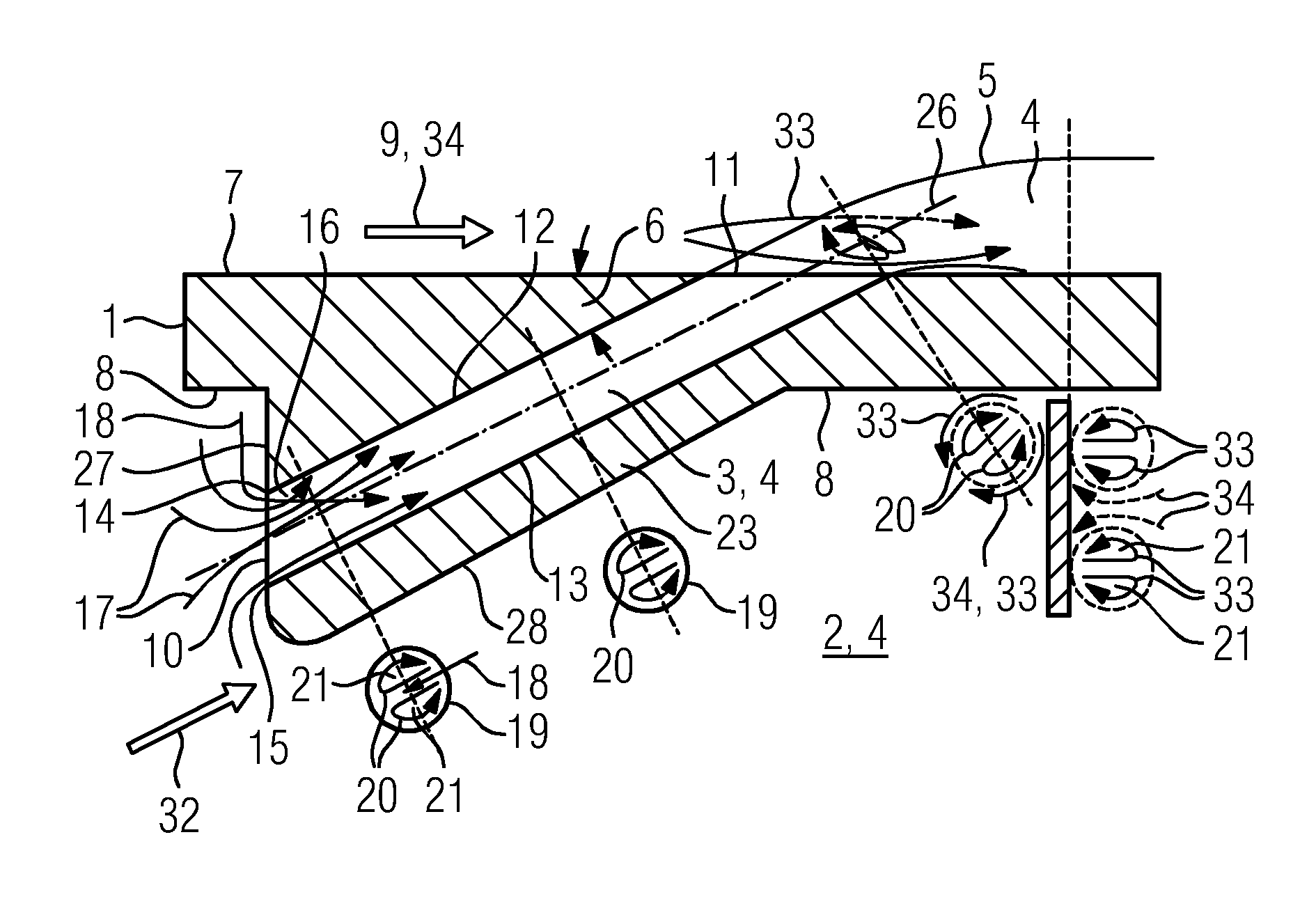
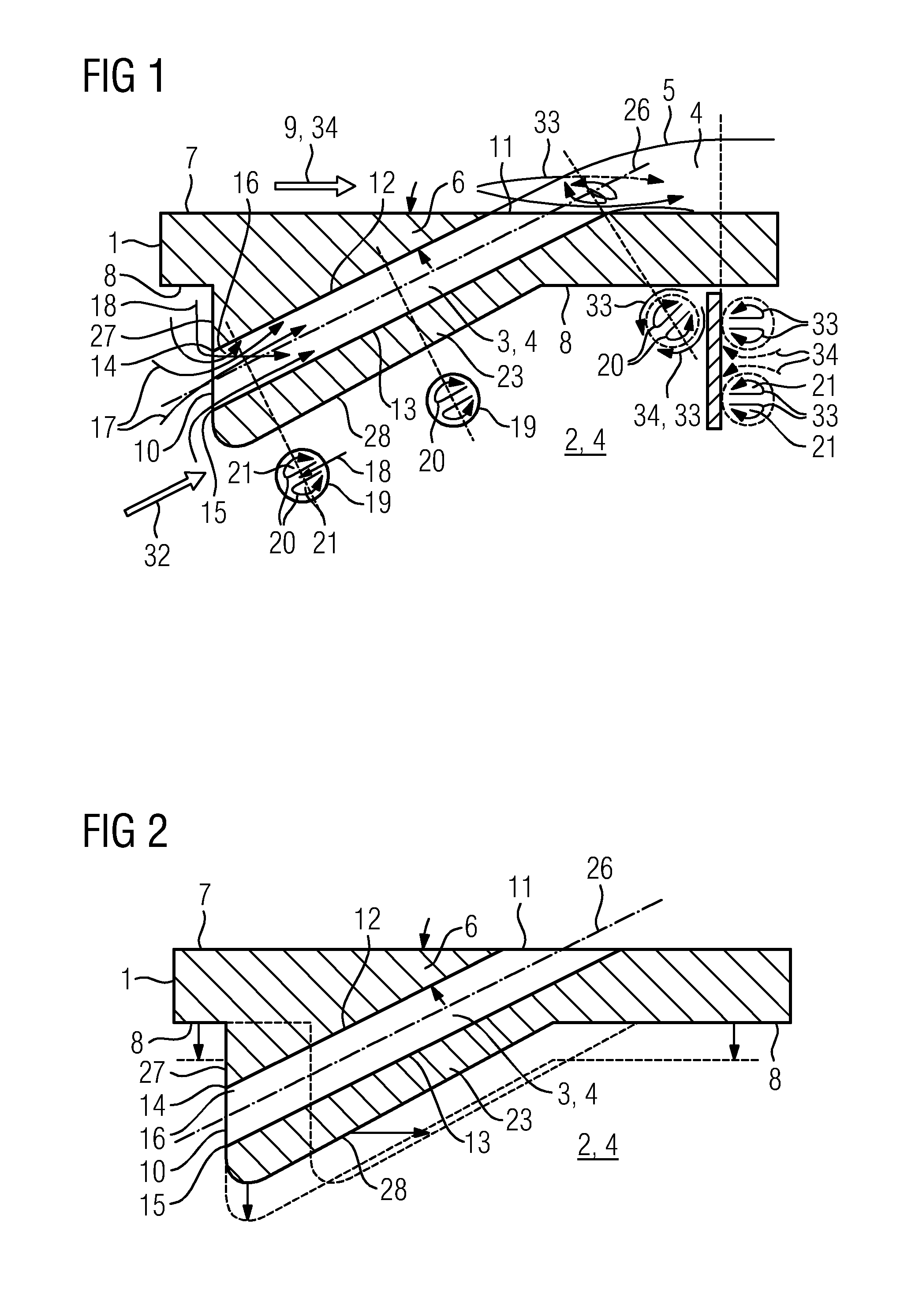
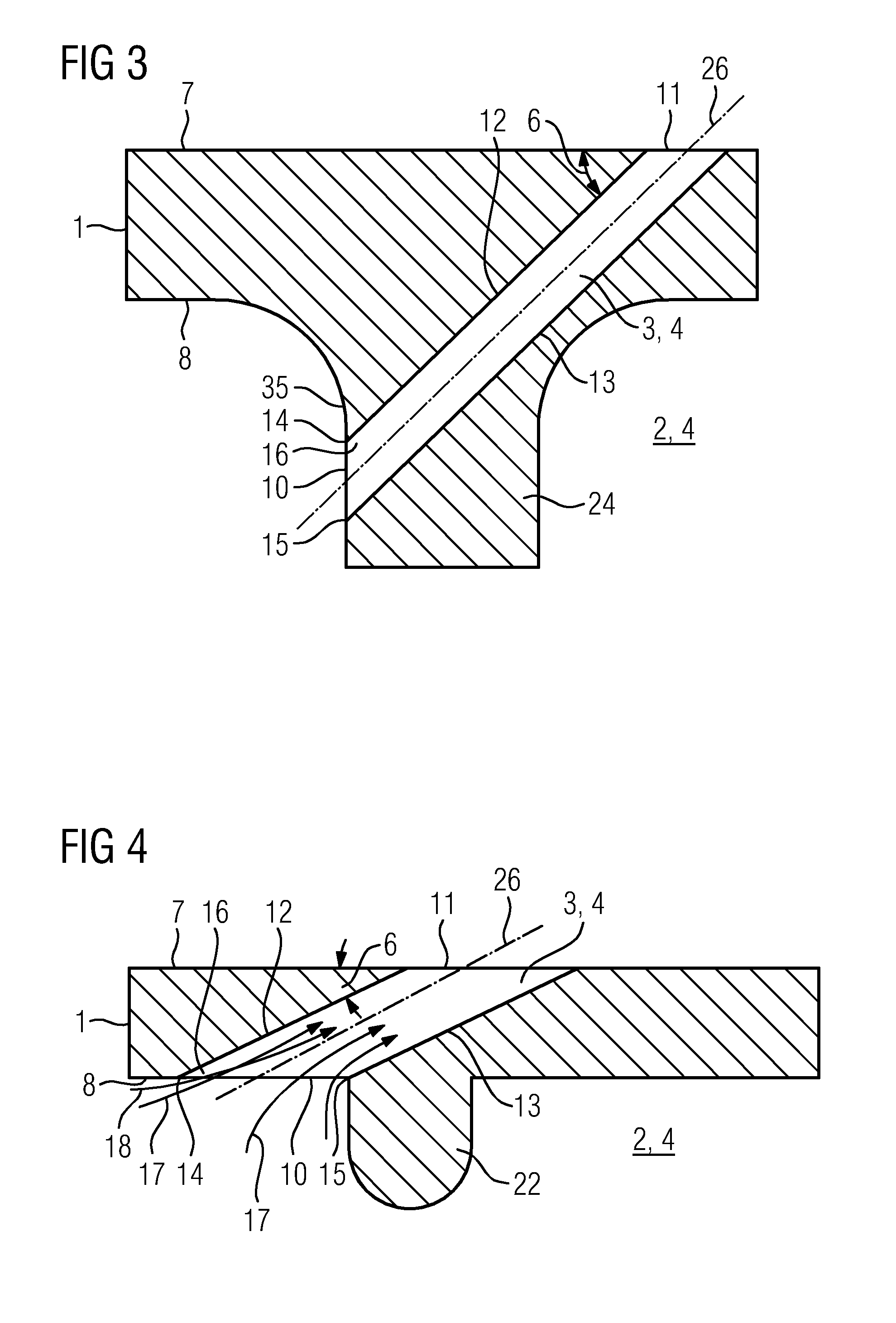
[0019]FIGS. 1 to 6 show a portion of an outer wall 1 of a turbine blade of a turbomachine. The outer wall 1 delimits an inner cavity 2 and has an outer face 7 and an inner face 8. When the turbomachine is in operation, a hot gas flow 34 occurs on the outer face 7, with a hot gas main flow direction 9 which is parallel to the outer face 7 and which is directed toward the trailing edge of the turbine blade (not shown in the figures). A through duct 3 of circular cross section 19 is introduced into the outer wall 1 and is inclined with respect to the trailing edge of the turbine blade in the through-flow direction directed from the inside outward and forms an acute inclination angle 6 with the outer face 7.

[0020]The through duct 3 in FIGS. 1 to 6 has an entrance 10 on the inside and an exit 11 on the outside. Furthermore, the through duct 3 has an axis 26, an upstream side 12 and a downstream side 13. The entrance 10 of the through duct 3 has an upstream marginal portion 14 on the upst...


PUM


Abstract

A turbine blade for a turbomachine has an outer wall which delimits an inner cavity. Cooling fluid flows in the inner cavity. A through duct is arranged in the outer wall through which the cooling fluid flows from the inner cavity to an outside of the turbine blade. The through duct is inclined with respect to a trailing edge of the turbine blade, wherein a marginal portion of an entrance of the through duct is designed on an upstream side to be sharp-edged in relation to other marginal portions of the entrance such that a separation zone of a cooling fluid flow is formed in the through duct. A pair of swirls builds up in the through duct, wherein velocity vectors of the cooling fluid flow between the swirl centers point toward a downstream side of the through duct.

Description

FIELD OF INVENTION[0001]A turbine blade for a turbomachine, the turbine blade being film-cooled, is provided.BACKGROUND OF INVENTION[0002]A turbomachine, in particular a gas turbine, has a turbine in which hot gas, which has previously been compressed in a compressor and heated in a combustion chamber, is expanded in order to perform work. For high mass flows of the hot gas and therefore for high power output ranges of the gas turbine, the turbine is designed in an axial type of construction, the turbine being formed by a plurality of blade rings lying one behind the other in the through-flow direction. The blade rings have moving blades and guide vanes arranged over the circumference, the moving blades being fastened to a rotor of the gas turbine and the guide vanes being fastened to the casing of the gas turbine.[0003]The thermodynamic efficiency of the gas turbine is the higher, the higher the inlet temperature of the hot gas into the turbine is. By contrast, limits are placed up...

Claims


Application Information

Patent Timeline
Patent Type & Authority Applications(United States)
IPC IPC(8): F01D25/12
CPCF01D25/12F01D5/186F05D2260/209F05D2260/2212
Inventor HESELHAUS, ANDREAS
Owner SIEMENS AG
Why Eureka
Try Eureka