
Front wheel stabilizing device for an electric motor-driven wheeled vehicle

a technology of stabilizing device and front wheel, which is applied in the direction of electric propulsion mounting, wheelchair/patient conveyance, transportation and packaging, etc., can solve the problems of easy damage, unsightly, and weak structure of the main frame, and achieve the effect of improving anti-tipping stability

Inactive Publication Date: 2007-05-24
CHAO YA CHEN
View PDF9 Cites 23 Cited by
  • Summary
  • Abstract
  • Description
  • Claims
  • Application Information

AI Technical Summary

Benefits of technology

"The present invention provides a front wheel stabilizing device for electric motor-driven wheeled vehicles that can be easily assembled without weakening the main frame and has improved anti-tipping stability. The device includes a mount that is secured to the front side of the main frame, an axle that connects two side plates, a wheel mounting member with a tubular head and a cantilever arm, and a stabilizing wheel that can roll on the axle. The stabilizing wheel can yield under jolting force to displace from a more tractive position to a less tractive position. A torsion spring is used to bias the stabilizing wheel back to the more tractive position."

Problems solved by technology

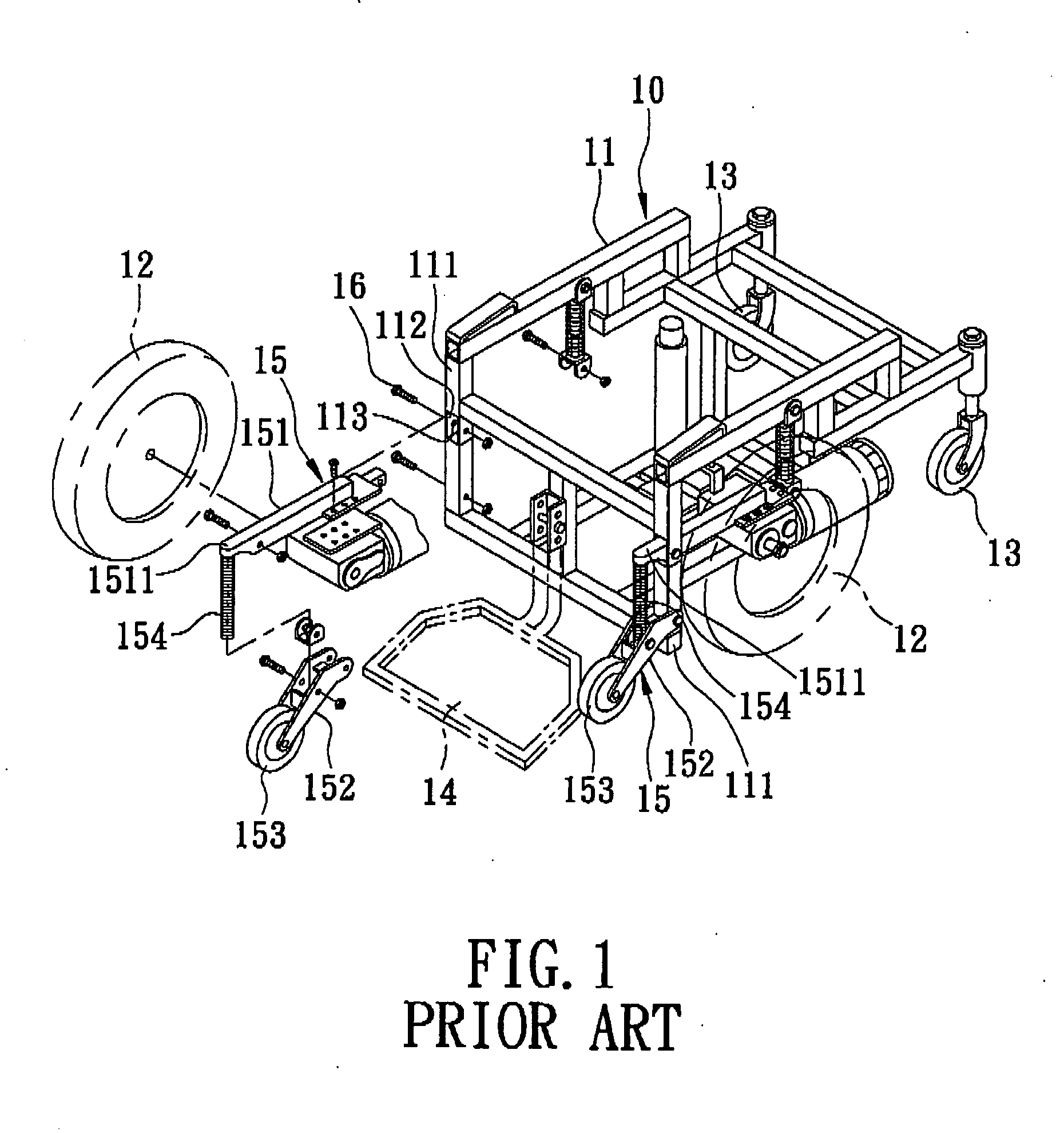
However, the upright posts 111 need to be formed with the insert holes 112 for passage of the support rods 151, and the lock holes 113 for securing the support rods 151 to the upright posts 111, thereby resulting in weakening of the structure of the main frame 11 and complicating the manufacturing process.
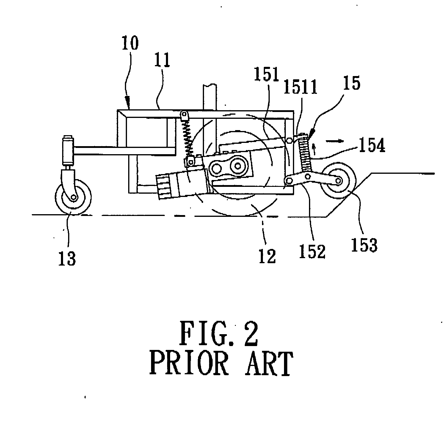
Moreover, as the front segments 1511 of the support rods 151 extend forwardly of the main frame 11 for the compression springs 154 to be mounted thereon, they are liable to be damaged as well as unsightly.
U.S. Pat. No. 5,848,658 and U.S. Pat. No. 6,460,641 also disclose electric power wheelchairs, which, however, suffer from the aforesaid drawbacks as well.

Method used


Image

  • Front wheel stabilizing device for an electric motor-driven wheeled vehicle
  • Front wheel stabilizing device for an electric motor-driven wheeled vehicle
  • Front wheel stabilizing device for an electric motor-driven wheeled vehicle

Examples


Embodiment Construction

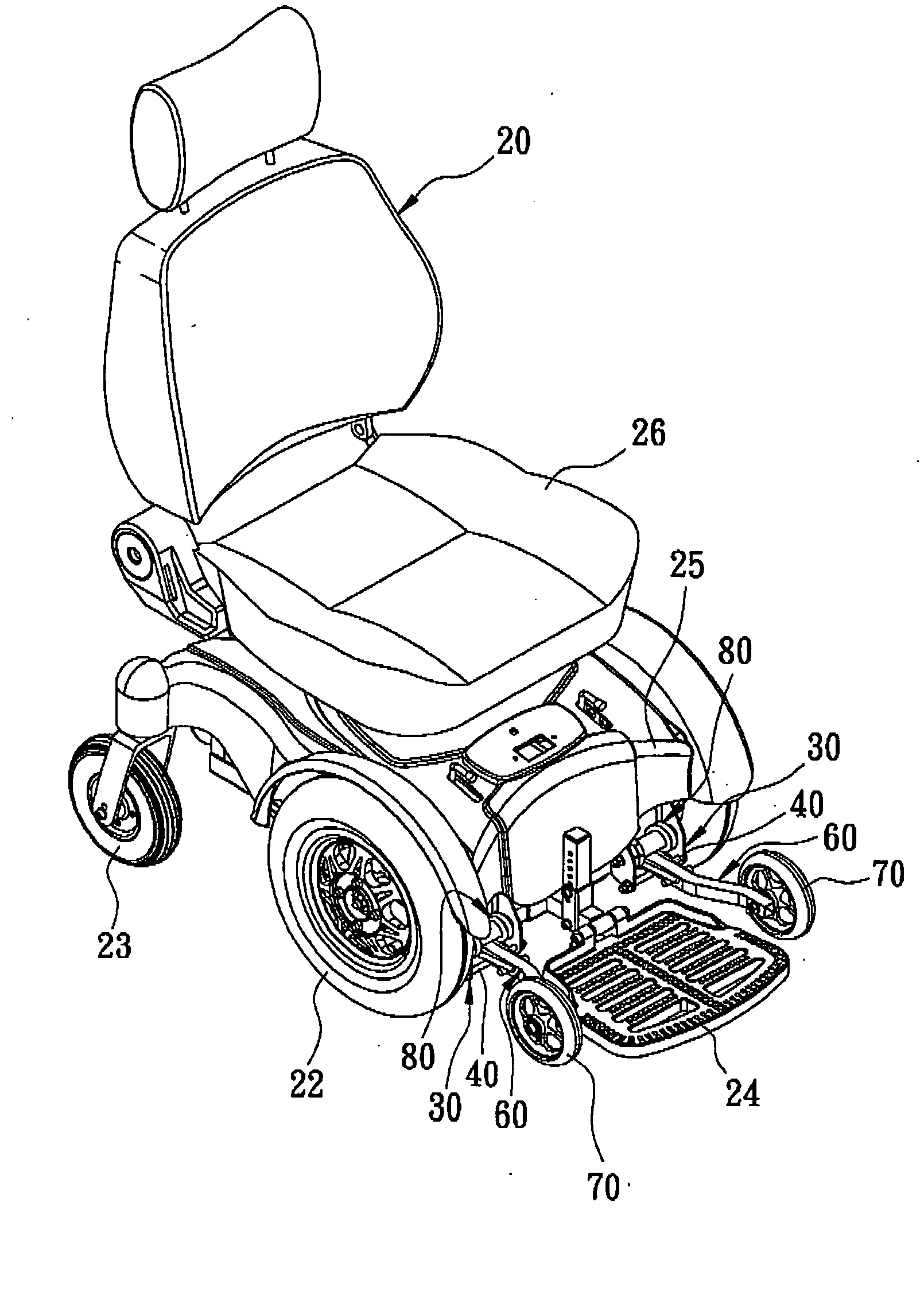
[0022] Referring to FIGS. 3 and 4, the preferred embodiment of a front wheel stabilizing device according to the present invention is adapted to be assembled to an electric motor-driven wheeled vehicle 20, such as an electric power-driven wheelchair. The wheeled vehicle 20 has a main frame 21 for supporting a vehicle seat 26 thereon, a pair of front drive wheels 22 mounted proximate to a front side of the main frame 21 to be rotatable relative thereto about a driving wheel axis in a transverse direction for propelling the wheeled vehicle 20 along a ground surface, a pair of rear caster wheels 23 mounted to a rear side of the main frame 21, and a footrest 24 mounted on the front side of the main frame 21. The main frame 21 includes a pair of front upright posts 211, a pair of rear upright posts 212, and a plurality of crossbars 213 interposed between the front upright posts 211 and the rear upright posts 212. A shell 25 is disposed to cover the main frame 21.

[0023] With further refe...


PUM


Abstract

A front wheel stabilizing device includes a mount adapted to be secured to a main frame of an electric motor-driven wheeled vehicle, and an axle disposed between two side plates of the mount. A wheel mounting member has a tubular head which is rotatably sleeved on the axle, and a cantilever arm which extends from the tubular head forwardly to terminate at a wheel-carrying end for mounting a stabilizing wheel thereon. The stabilizing wheel can yield under a jolting force that arises as a result of movement of the stabilizing wheel over an uneven ground so as to displace from a more tractive position to a less tractive position. A torsion spring has a coiled segment which is wound on the tubular head, and two urging ends which abut against the mount and the cantilever arm, respectively, so as to bias the stabilizing wheel downwardly, thereby restoring the stabilizing wheel from the less tractive position back to the more tractive position.

Description

BACKGROUND OF THE INVENTION [0001] 1. Field of the Invention [0002] This invention relates to a front wheel stabilizing device for an electric motor-driven wheeled vehicle, more particularly to a front wheel stabilizing device to prevent tipping of the wheeled vehicle. [0003] 2. Description of the Related Art [0004] A conventional electric motor-driven wheelchair is generally provided with a front wheel stabilizing device to improve tracking upon undulating or irregular surfaces and to provide anti-tip stability. FIGS. 1 and 2 show an electric power wheelchair 10 disclosed in Taiwanese patent publication No. 370866. The wheelchair 10 includes a main frame 11, two front drive wheels 12 mounted proximate to a front side of the main frame 11, two rear caster wheels 13 mounted on a rear aide of the main frame 11, and a footrest 14 and two front stabilizing devices 15 mounted on the front side of the main frame 11. [0005] Each of the front stabilizing devices 15 includes a support rod 15...

Claims


Application Information

Patent Timeline
Patent Type & Authority Applications(United States)
IPC IPC(8): B60K1/00
CPCA61G5/042A61G5/06A61G2005/1078A61G2005/121A61G2005/128Y10S180/907A61G5/1078A61G5/121A61G5/128
Inventor CHAO, YA-CHEN
Owner CHAO YA CHEN
Learn More