

Stripping tower for CO conversion condensate
A technology of condensate and stripper, which is applied in the field of CO-shift condensate stripper, can solve the problems of increasing the water consumption of stripping gas condensation cycle, the consumption of low-pressure steam, the complex control of the stripper operating system, and the lack of stability. The effect of prolonging the period of stable operation, solving the blockage of ammonium salt crystals and reducing the dosage
Active Publication Date: 2013-03-13
CHINA PETROLEUM & CHEM CORP +2
View PDF7 Cites 7 Cited by
- Summary
- Abstract
- Description
- Claims
- Application Information
AI Technical Summary
Problems solved by technology
[0004] The main disadvantages of setting up a single stripper are as follows: First, the stripping gas stripped from the top of the tower by the CO shift condensate stripper contains both carbon dioxide and ammonia, so that in the subsequent condensation process, carbon dioxide and ammonia are easily Ammonium salt crystals are generated, which block the pipes and condensers; followed by the conversion of condensate entering the condensate stripping tower from different upstream equipment, and the mixed flow of several fluids with different temperatures, simultaneously from the condensate stripping tower The upper part of the side wall is added at one time, and the temperature gradient of different streams is not fully utilized, that is to say, the temperature and energy utilization of several streams is not scientific and reasonable. As a result, the stripping gas temperature of the condensate stripping tower is relatively high. High, increasing the water consumption of the condensation cycle of th
Method used
View moreImage
Smart ImageViewing Examples

Examples
 PUM
 Abstract
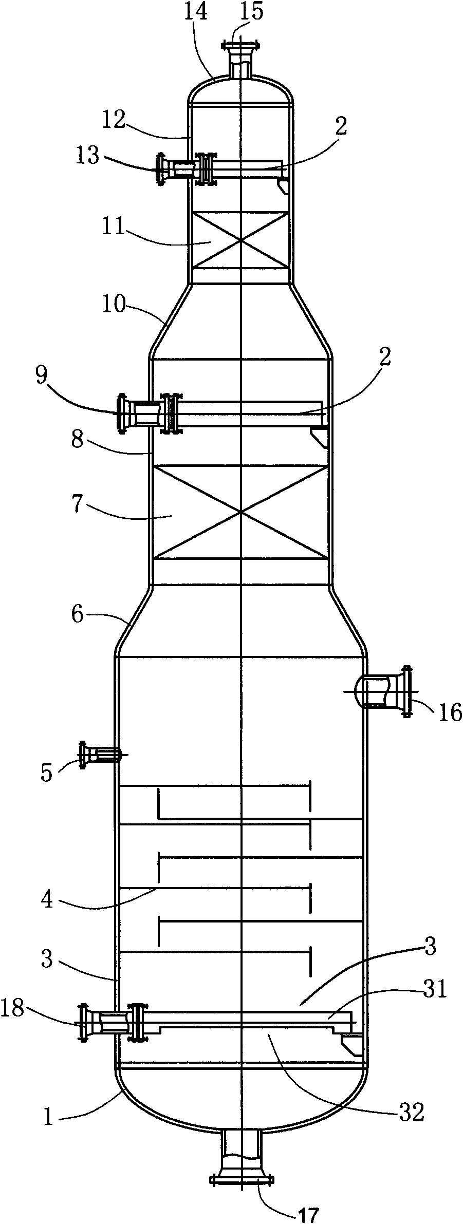
The invention relates to a stripping tower for a CO conversion condensate, which comprises a tower body, wherein a first steam stripping gas outlet; a liquid outlet, through which conversion steam stripping condensate is discharged, is formed in the bottom of the tower body; a low pressure steam inlet is formed in the lower part on the side wall of the tower body; and a plurality of condensate inlets, through which condensate enters into the tower body, are formed in the middle upper part on the side wall of the tower body. The stripping tower is characterized in that the number of the condensate inlets is large; the condensate inlets are arranged at intervals side by side; and a second steam stripping gas outlet, through which ammonia steam is discharged, is formed in the middle on the side wall of the tower body. Compared with the prior art, the invention has the advantages that the potential temperatures and the energy gradients of different conversion condensates are utilized scientifically and reasonably, so as to save the consumption of low pressure steam used for steam stripping, reduce the consumption of circulating cooling water used for a rear system to condensate steam stripping gas, eliminate a heat recovering device which is necessary in a post process, avoid the phenomenon that carbon dioxide and ammonia exist at the same time in a condenser system, effectively solve the problem of blockage caused by ammonium salt crystallization, and prolong the stable operation period of a conversion device.
Description
technical field [0001] The invention relates to a CO shift condensate stripper. Background technique [0002] The synthesis gas produced by coal gasification or residual oil gasification contains a relatively high concentration of CO gas. When the synthesis gas is used to produce products such as methanol or urea, a CO conversion unit is required to convert part or absolute of the synthesis gas by reacting with water vapor. Most of the CO is removed, producing hydrogen gas equimolar to CO. In order to increase the conversion rate and control the bed temperature in the shift reaction, it is generally required to add an excess of water vapor, and the remaining water vapor in the shift reaction is cooled in the waste heat recovery system to become a condensate, which is called a shift condensate. Usually, the shift condensate contains a small amount of gases such as ammonia and carbon dioxide dissolved in it, and it needs to be sent to the shift condensate stripping tower to b...
Claims
Login to View More Application Information
Patent Timeline
 IPC IPC(8): C02F1/04C02F1/20B01D3/38
CPCY02P70/10
Inventor许仁春陈莉施程亮张骏驰黄彬峰陆亚东李绍红唐永超徐洁卢新军张晓宁
OwnerCHINA PETROLEUM & CHEM CORP