
marking wheel

A scribing wheel and shape wheel technology, applied in glass manufacturing equipment, metal processing, fine working devices, etc., to achieve the effect of improving the strength of the end face, good grip, and improving the strength of the end face

Inactive Publication Date: 2015-09-16
MITSUBOSHI DIAMOND IND CO LTD
View PDF5 Cites 0 Cited by
  • Summary
  • Abstract
  • Description
  • Claims
  • Application Information

AI Technical Summary

Problems solved by technology

However, if the blade tip load exceeds a certain level, a long vertical crack can be formed, but the internal strain of the plastically deformed region along the scribed line on the surface of the glass substrate becomes saturated, thereby generating a horizontal crack and causing undesirable Cuttings (glass shavings)

Method used


Image

  • marking wheel
  • marking wheel
  • marking wheel

Examples


Embodiment Construction

[0061] Hereinafter, embodiments of the present invention will be described with reference to the drawings. However, the embodiments shown below represent an example of a scribing wheel for realizing the technical idea of ​​the present invention, and are not intended to limit the present invention to this scribing wheel, and can be similarly applied to those included in the scope of the claims. Other embodiments of the marking wheel. In addition, in the drawings shown below, in order to recognize each structure easily, the scale is suitably changed for each structure part, and it is not necessarily shown according to an actual size or an angle.

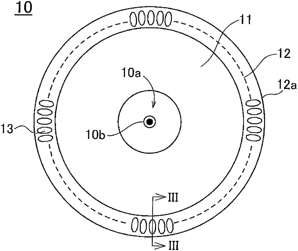
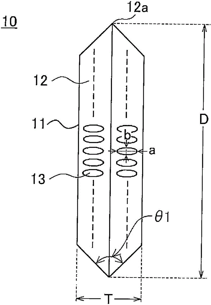
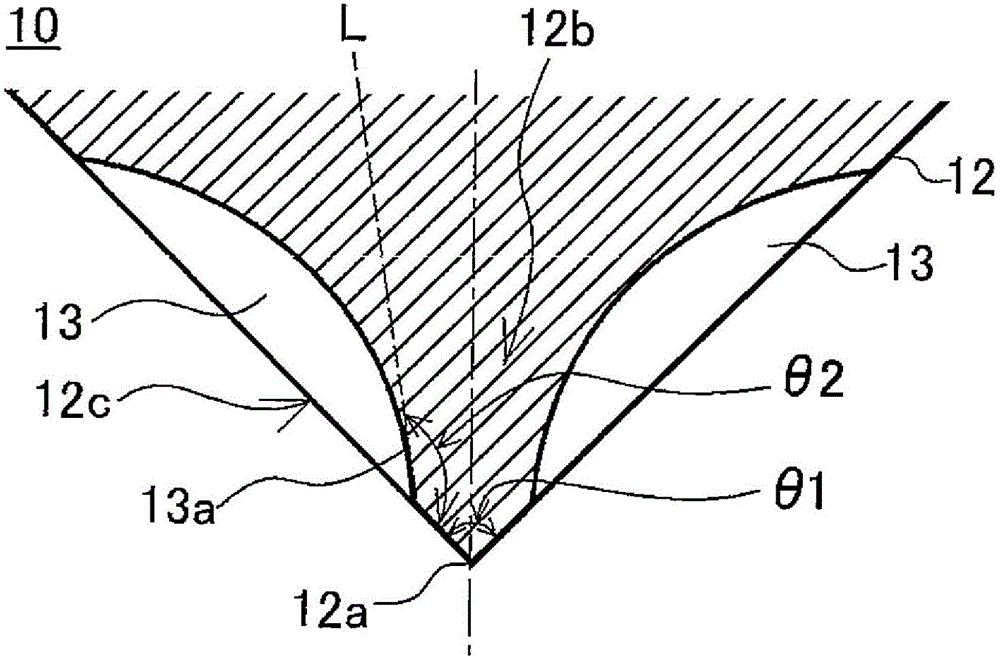
[0062] First, refer to Figure 1 ~ Figure 3 The scribing wheel of the embodiment will be described. in addition, figure 1 It is a side view of the scribing wheel of embodiment. figure 2 yes figure 1 front view of a scribing wheel. image 3 is along figure 1 An enlarged sectional view of line III-III.

[0063] Such as Figu...


PUM

PropertyMeasurementUnit
thicknessaaaaaaaaaa

Abstract

PURPOSE: A scribing wheel is provided to have a brittle substrate with a cross section with improved strength. CONSTITUTION: A scribing wheel(10) has a blade end which forms a ridge part along the circumference of a disk-shaped wheel. A concave cut-out portions(13) are formed from the blade end in a predetermined position. The front end portion has a thin-wall portion(12b) and a thick-wall portion(12c).

Description

technical field [0001] The present invention relates to a scribing wheel, in particular to a scribing wheel which has good grip between a blade tip and a brittle substrate, and which can improve the end surface strength of the brittle substrate to be scribed. Background technique [0002] Conventionally, in the manufacturing steps of flat panel display panels such as liquid crystal display panels and organic electroluminescence (EL, electroluminescence) panels, solar cells, and the like, a step of cutting brittle material substrates such as mother glass substrates is provided. In the above cutting step, the scribing wheel is rotated on the surface of the brittle substrate to form scribed lines while applying a load in accordance with various conditions such as the material and thickness of the brittle substrate to the scribing wheel. The force cuts the brittle substrate along the scribe line, thereby manufacturing a single panel or glass substrate. [0003] As these scribin...

Claims


Application Information

Patent Timeline
Patent Type & Authority Patents(China)
IPC IPC(8): C03B33/10
CPCB26D3/085B28D5/00C03B33/033C03B33/107Y02P40/57
Inventor 中垣智贵近藤干夫
Owner MITSUBOSHI DIAMOND IND CO LTD
Features
  • Generate Ideas
  • Intellectual Property
  • Life Sciences
  • Materials
  • Tech Scout
  • Unparalleled Data Quality
  • Higher Quality Content
  • 60% Fewer Hallucinations
Learn More