System and method for monitoring cross-hole electromagnetic transient

A monitoring system and electromagnetic technology, which are applied to earth-moving drilling, wellbore/well components, etc., can solve the problems of increasing difficulty in tapping potential, shallow detection depth, low resolution, etc., and achieve accurate and reliable monitoring results, simple structure and low cost. low cost effect

Inactive Publication Date: 2013-03-13
褚万泉
View PDF5 Cites 20 Cited by
  • Summary
  • Abstract
  • Description
  • Claims
  • Application Information

AI Technical Summary

Problems solved by technology

[0002] Conventional logging technology is suitable for single well measurement, which can accurately reflect the bottom layer information near the wellbore, but its detection depth is shallow, and it is difficult to reflect the regional formation information, especially the interwell formation information. A large area is flooded, the oil-water relationship is complex, and the distribution of remaining oil is scattered. It is more difficult to tap the potential and the effect of tapping the potential is getting worse.
Seismic detection uses long-distance acoustic detection technology. Although the detection range is large, its resolution is low. The measurement information is sensitive to reservoir rocks and cannot accurately reflect the type and distribution of fluids. It is difficult to efficiently perform the current oil reservoir detection tasks.

Method used


Image

  • System and method for monitoring cross-hole electromagnetic transient
  • System and method for monitoring cross-hole electromagnetic transient
  • System and method for monitoring cross-hole electromagnetic transient

Examples


Embodiment Construction

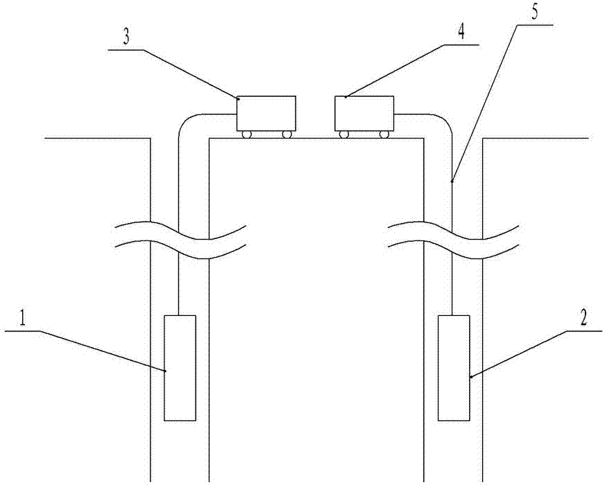
[0024] Such as figure 1 Shown is a schematic diagram of the interwell electromagnetic transient logging structure.

[0025] When conducting cross-well electromagnetic transient monitoring, first place a transmitter string in the corresponding target section of the oil production well to form a transmitter system, so that it is connected to the ground instrument through a cable to transmit signals;

[0026] The second is to place a receiver string in the corresponding target interval of the selected well to form a receiver system, which is also connected to the surface instrument through a cable to transmit signals;

[0027] Then the ground instrument controls the transmitter string to emit the transient electromagnetic signal, and the receiver string receives the corresponding signal of the formation secondary field generated by the transient electromagnetic signal, and the receiver string records the signal and transmits it to the data processing system of the ground ...


PUM


Abstract

The invention relates to the technical field of oil production engineering test in the oil field, in particular to a system and a method for monitoring a cross-hole electromagnetic transient. The method comprises the steps as follows: placing an ejector pipe column in the corresponding destination section layer of a signal emission well, and connecting the ejector pipe column with a ground instrument by using a cable; placing a receiver pipe column in the corresponding destination section layer of a signal receiving well, and connecting the receiver pipe column with the ground instrument by using the cable; controlling the ejector pipe column to emit an electromagnetic transient signal by the ground instrument, receiving a corresponding stratic secondary field signal generated by the electromagnetic transient signal by the receiver pipe column, and recording and transmitting the signal to a data processing system of the ground instrument for analysis by the receiver pipe column; and monitoring the flowing situation of a fluid in deep stratum through tomography obtained according to measurement results, and generating a formation resistivity profile map by integrating the characteristics of electromagnetic induction and tomography so as to make accurate positioning analysis on an oil storage layer. The method has the advantages of flexibility, low cost and high efficiency.

Description

technical field [0001] The invention relates to the technical field of oil field production engineering testing. In particular, it relates to a cross-well electromagnetic transient monitoring system and a monitoring method thereof. Background technique [0002] Conventional logging technology is suitable for single well measurement, which can accurately reflect the bottom layer information near the wellbore, but its detection depth is shallow, and it is difficult to reflect the regional formation information, especially the interwell formation information. A large area is flooded, the relationship between oil and water is complicated, and the distribution of remaining oil is scattered. It is more difficult to tap the potential and the effect of tapping the potential is getting worse. Seismic detection uses long-distance acoustic detection technology. Although the detection range is large, its resolution is low. The measurement information is sensitive to reservoir rocks and...

Claims


Application Information

Patent Timeline
Patent Type & Authority Applications(China)
IPC IPC(8): E21B49/00E21B49/08
Inventor 褚万泉胡瑞华吕晶刘安朱军齐红玉
Owner 褚万泉
Why Eureka
Try Eureka