Method for creating internal dumping conditions of strip mine

An internal dumping and open-pit mine technology, applied in open-pit mine mining, earthwork drilling, special mining, etc., can solve the problems of short strike length, large inclination extension, and small distribution range, and save transportation costs and transportation distances. The effect of the recent and extended service life

Inactive Publication Date: 2013-03-13
马钢集团设计研究院有限责任公司 +1
4 Cites 27 Cited by

AI-Extracted Technical Summary

Problems solved by technology

[0007] The purpose of the present invention is exactly for the above-mentioned defect that prior art exists, provides a kind of method that creates the soil discharge condition in the open-pit mine, solves metal, non-metal ore deposit mostly is inclined or sharply inclined ore body, and strike length is short, ...

Abstract

The invention discloses a method for creating internal dumping conditions of a strip mine, which is characterized by comprising the steps of adopting an exploitation zone, exploiting in a segmented way, carrying out steep slope mining advancement to create internal dumping conditions, and also comprising the step of sufficiently utilizing the areas of the stope and the blasting warning line as a 'transfer station' to carry out internal dumping. The step of internal dumping is carried out according to the following steps: (1) firstly exploiting stripped rocks, and adopting a footstep separated manner to temporarily stack the rocks on the other part of the rocks which are not exploited temporarily in the range of 300m blasting warning line away from the upper opening of the stope; (2) constantly stretching downwards and advancing lengthwise along the stope, so that the primarily-exploited part reaches the final boundary first, and the rocks on the other part are moved to the mining pit of the primarily-exploited part, wherein a footstep separated manner is adopted for stacking; and (3) continuing to advance lengthwise in the stope to cause the space of the mining pit to be enlarged constantly, and moving the rocks in the range of the blasting warning line into the mining pit gradually. The method has the advantages of not occupying other lands, prolonging the service life of the internal dump, and saving cost.

Application Domain

Open-pit mining

Technology Topic

Image

  • Method for creating internal dumping conditions of strip mine
  • Method for creating internal dumping conditions of strip mine

Examples

  • Experimental program(1)

Example Embodiment

[0020] In the following, with reference to the accompanying drawings, through the description of the embodiments, the method of the present invention for creating the conditions for dumping in the open-pit mine will be further explained in detail.
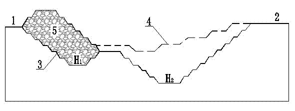
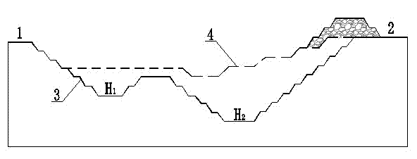
[0021] As shown in the figure, the Gushan iron deposit is shallowly buried, and the west wing extends relatively large, while the east wing extends relatively shallow; it is a semi-annular in the horizontal direction, and the south is broken by rock mass. Therefore, the designed minimum mining elevations at the east and west ends of the open-pit boundary are different. The eastern minimum mining elevation (H 1 ) -106m, the lowest mining elevation in the west (H 2 ) -166m.
[0022] According to the current state of mining in the Gushan quarry, if the east and west ends are mined at the same time, the stripped rock and soil will have no place to drain. Therefore, the stripping position of the stope is optimized and adjusted, and the eastern part of the stope is about to be mined to the final boundary of the stope (3), and the uppermost step of the western end of the stope is not yet supported. First, the eastern part of the stope is mined (1). The stripped rock and soil are temporarily discharged from the upper part of the west side of the stope 2 to the range of the blasting warning line (4), and the east side of the stope (1) after mining is completed, then the west side of the stope (2) is mined.
[0023] After the mining in the eastern part of the stope (1) is completed, a relatively large pit is formed in the eastern part of the stope, which can be used as an internal dump for mining in the western part of the stope (2). First, the rock and soil piled in the west (2) of the stope are transferred to the east of the stope (1) by using the development and transportation road inside the stope, and then the inner dump (5) design and stability study are carried out to determine a reasonable Dumping structural parameters, and then mining the western part of the stope (2), and the stripped rock and soil are stacked in the inner dumping field (5).
[0024] The structural parameters of the internal dump (5) are: stage height 10m, safety platform width 16m, step slope angle 34°, and overall slope angle 19-21°.

PUM

no PUM

Description & Claims & Application Information

We can also present the details of the Description, Claims and Application information to help users get a comprehensive understanding of the technical details of the patent, such as background art, summary of invention, brief description of drawings, description of embodiments, and other original content. On the other hand, users can also determine the specific scope of protection of the technology through the list of claims; as well as understand the changes in the life cycle of the technology with the presentation of the patent timeline. Login to view more.

Similar technology patents

Classification and recommendation of technical efficacy words

People also interested in

Why Eureka
Try Eureka