Bellows mechanical sealing device with self-circulation function

A mechanical seal device, bellows technology, applied in the direction of engine seals, mechanical equipment, engine components, etc., can solve the difficulty of reasonable design and selection of mechanical seals, the short axial space of the pump body seal cavity, and the large heat load of seal flushing. and other problems, to achieve the effect of good followability, compact structure and improved cooling efficiency

Active Publication Date: 2013-03-13
DONGGUAN HUAHUI PRECISION MASCH CO LTD
View PDF10 Cites 8 Cited by
  • Summary
  • Abstract
  • Description
  • Claims
  • Application Information

AI Technical Summary

Problems solved by technology

In order to reduce the overall size of the pump body, improve the bending strength of the pump shaft, and improve the movement accuracy of the pump shaft, the axial space of the pump body seal cavity is objectively short, so the reasonable design and selection of mechanical seals It causes difficulties, especially it is difficult to design as a cartridge mechanical seal, the thermal load of seal flushing is large, and the thermal conductivity of the sealing end face is poor, which leads to the instability of the liquid film, resulting

Method used


Image

  • Bellows mechanical sealing device with self-circulation function
  • Bellows mechanical sealing device with self-circulation function
  • Bellows mechanical sealing device with self-circulation function

Examples


Embodiment Construction

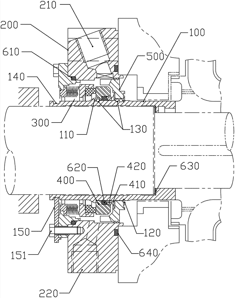
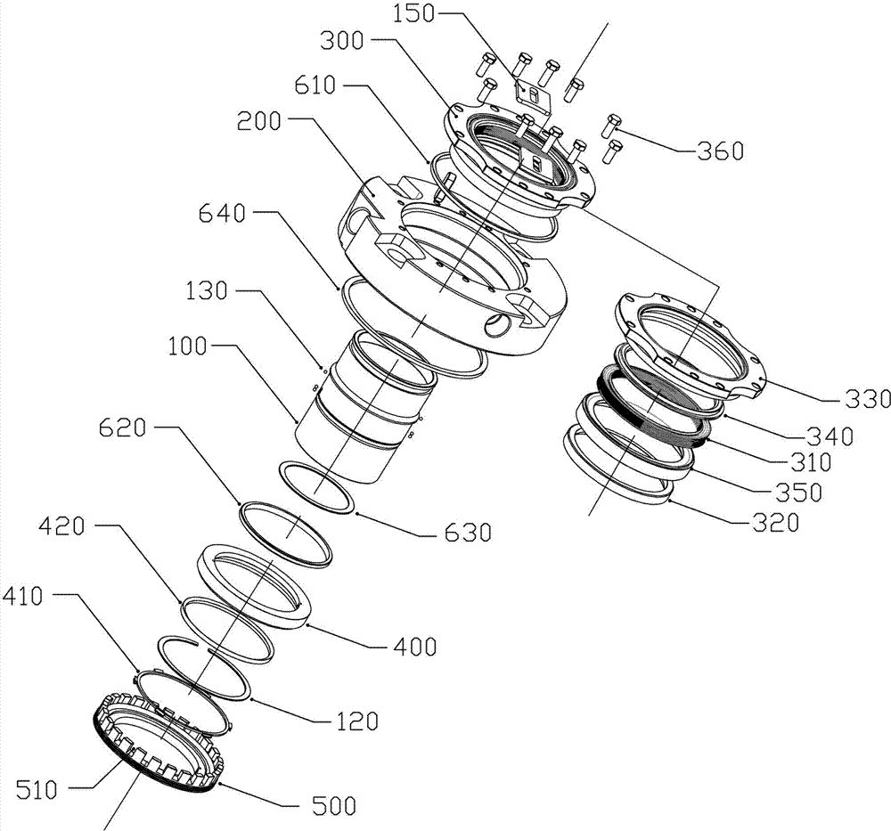
[0020] refer to figure 1 and figure 2 , a bellows mechanical seal device with self-circulation, including a shaft sleeve 100, a sealing gland 200, an elastic compensation assembly 300, a moving ring 400, an auxiliary seal and a pump effect ring 500, and the sealing gland 200 is provided with a flushing outlet 210 The location of the flush inlet 220 and the flush outlet 210 corresponds to the outer wall of the pump effect ring 500 .

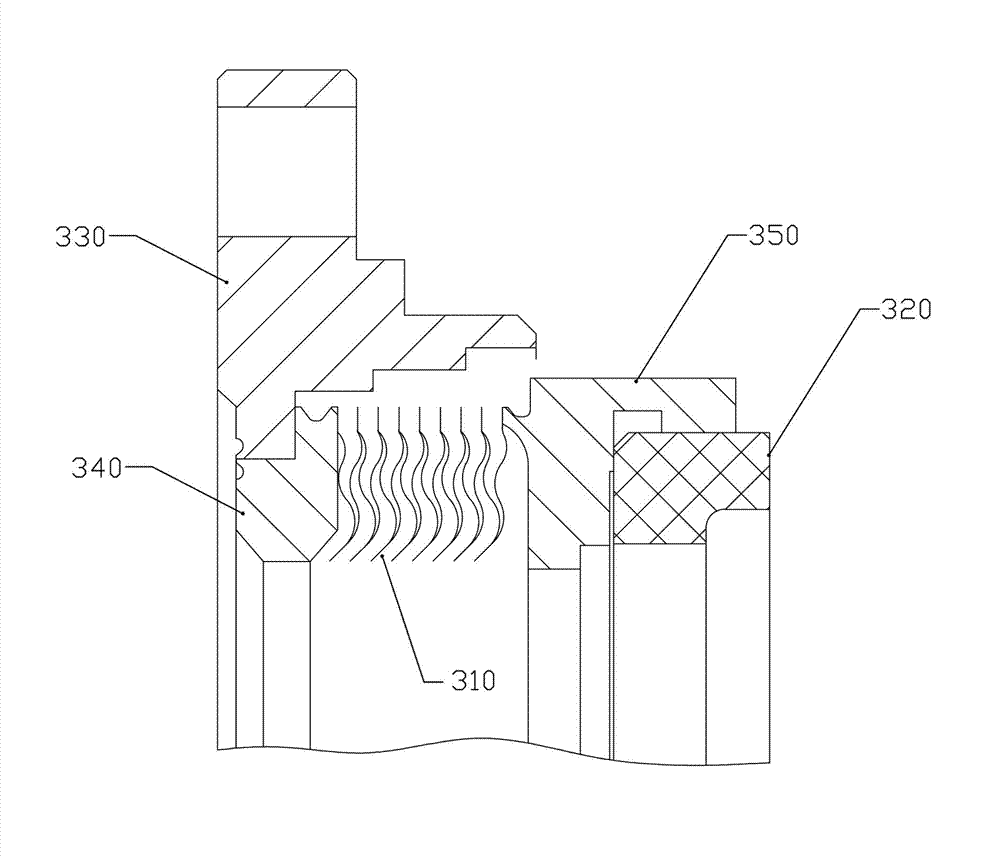
[0021] refer to image 3 The elastic compensation assembly 300 includes a bellows 310, a static ring 320, an annular end cover 330, a transition ring 340 and a static ring seat 350, the bellows 310 is a welded metal bellows, and the transition ring 340 and the static ring seat 350 are respectively sealed and welded to At both ends of the bellows 310, the static ring 320 is inlaid on the static ring seat 350, and the transition ring 340 is welded on the end cover 330, and the end cover 330 is fixed on the sealing gland 200 by eight uniformly dis...


PUM

PropertyMeasurementUnit
Widthaaaaaaaaaa

Abstract

The invention discloses a bellows mechanical sealing device with a self-circulation function, which comprises a shaft sleeve, a sealing gland, an elastic compensation component, a moving ring, an auxiliary sealing part and a pump ring. The elastic compensation component comprises a bellows, a static ring and an end cover; the static ring and the end cover are connected to both ends of the bellows in a sealing manner; the end cover is fixed on the sealing gland; the outer wall of the shaft sleeve is provided with a step; one side of the moving ring is abutted against the step; the pump ring is propped against the moving ring by a wave spring; a clamp spring is arranged on the shaft sleeve in a position outside the pump ring; the pump ring and the moving ring are clamped on the shaft sleeve by the clamp spring and the step; anti-rotating parts are respectively between the shaft sleeve and the moving ring and between the shaft sleeve and the pump ring; a ring-shaped clamping groove is formed in the shaft sleeve in a position outside the end cover; and a limiting plate is clamped in the clamping groove and is fixed on the sealing gland. The elastic compensation component is fixed with the sealing gland, the moving ring and the pump ring are clamped on the shaft sleeve by the step and the clamp spring and the sealing gland and the elastic compensation component are limited on the shaft sleeve by the limiting plate, so as to form a cartridge mechanical seal.

Description

technical field [0001] The invention relates to a mechanical seal device of a pump, in particular to a bellows mechanical seal device with self-circulation. Background technique [0002] Single-stage cantilever centrifugal pumps are the most widely used in fluid pumping. In order to reduce the overall size of the pump body, improve the bending strength of the pump shaft, and improve the movement accuracy of the pump shaft, the axial space of the pump body seal cavity is objectively short, so the reasonable design and selection of mechanical seals It causes difficulties, especially it is difficult to design as a cartridge mechanical seal, the thermal load of seal flushing is large, and the thermal conductivity of the sealing end face is poor, which leads to the instability of the liquid film, resulting in dry friction of the sealing surface and the tendency of premature failure. In order to reduce the thermal load in the sealed space, stabilize the liquid film and protect th...

Claims


Application Information

Patent Timeline
IPC IPC(8): F16J15/52
Inventor 郭文德
Owner DONGGUAN HUAHUI PRECISION MASCH CO LTD
Why Eureka
Try Eureka