Method for measuring object surface topography

A technology for the surface and shape of an object, which is applied in the direction of measuring devices, instruments, and optical devices, can solve the problems of small measurement range and harsh measurement conditions, and achieve the effects of improving imaging sensitivity, high-resolution imaging, and high-resolution accuracy

Inactive Publication Date: 2013-03-13
广东华快光子科技有限公司
View PDF7 Cites 22 Cited by
  • Summary
  • Abstract
  • Description
  • Claims
  • Application Information

AI Technical Summary

Benefits of technology

This patented describes a new way to measure how well things look like when they are being observed or scanned over them. It uses two types of lights: one called pulsed lasers that work together at different wavelength ranges (called frequencies) while another called ultrasonic waves). By combining these techniques, this technique allows us to make precise measurements even more accurate than previous methods such as interferometry. Additionally, we have developed various technologies related to detect changes caused by external factors affecting their appearance during observation processes. These improvements allow researchers to study materials better ways to create products without defective ones.

Problems solved by technology

Technological Problem: Existing Laser Non-Destrusion (LND) Surface Texture Measurements are limited because they require expensive equipment like microscopy devices which can damage sensitive materials during measurements. There exists an issue where these methods may lead to imprecise depth profiles when used alone without being able to accurately detect certain types of defects caused by external factors like impact force.

Method used


Image

  • Method for measuring object surface topography

Examples


Embodiment Construction

[0019] Embodiments of the present invention will be described in detail below in conjunction with the accompanying drawings.

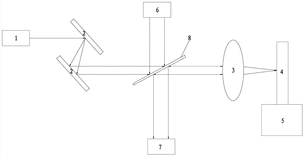
[0020] Firstly, the carrier envelope phase and repetition frequency of the optical comb 1 at the transmitting end and the optical comb 6 at the local oscillation end are precisely locked at the same time. Let the two optical combs have a small repetition frequency difference, and lock the two optical combs on the same frequency standard at the same time, so as to ensure the minimum relative frequency jitter between the two optical combs. The optical comb 6 at the local oscillation end uses a femtosecond laser comb light source, which has good spatial coherence and directionality, and can be directly contactless and without damaging the surface of the measured object. At the same time, the frequency uncertainty of the optical comb light source is small, which can ensure Accuracy and precision of measurements.

[0021] Then, using the spatial chirp tech...


PUM


Abstract

The invention discloses a method for measuring object surface topography. The method adopts a femtosecond laser optical comb light source and is a novel non-contact optical surface topography imaging method, double-optical-comb beat frequency detection technology and pulse space chirp technology are combined, spatial position information measurement is converted into distinguishable measurement of detecting light spectrum, ultra-sensitive optical surface topography detection with higher resolution accuracy is achieved, a stable phase-frequency relation of the optical comb light source is utilized, imaging sensitivity of an instrument is improved through a coherent measurement way, high solution imaging can be achieved on the surface topography by using optical comb heterodyning beat frequency detection and frequency spectrum coherent identification technology, a double-optical comb and a nanometer mobile platform are used for scanning an object to be tested automatically, a spatial beam expanding function of a detection light spot is combined, and large-area ultra-sensitive rapid imaging can be achieved on the surface of the object to be tested.

Description


Claims


Application Information

Patent Timeline
Owner 广东华快光子科技有限公司
Why Eureka
Try Eureka