Imageable elements and methods useful for providing waterless printing plates

Inactive Publication Date: 2009-12-10
EASTMAN KODAK CO
View PDF16 Cites 5 Cited by
  • Summary
  • Abstract
  • Description
  • Claims
  • Application Information

AI Technical Summary

Benefits of technology

[0048]We also found that the silicone debris is removed during development in relatively small

Problems solved by technology

The use of such films is expensive and tedious.
However, the use of masks to produce waterless printing plates is expensive and requires complicated processing methods.
Ablative imaging requires very high imaging energy (the imageable elements have relatively slow imaging speed) and creat

Method used


Image

  • Imageable elements and methods useful for providing waterless printing plates
  • Imageable elements and methods useful for providing waterless printing plates
  • Imageable elements and methods useful for providing waterless printing plates

Examples


invention example 1

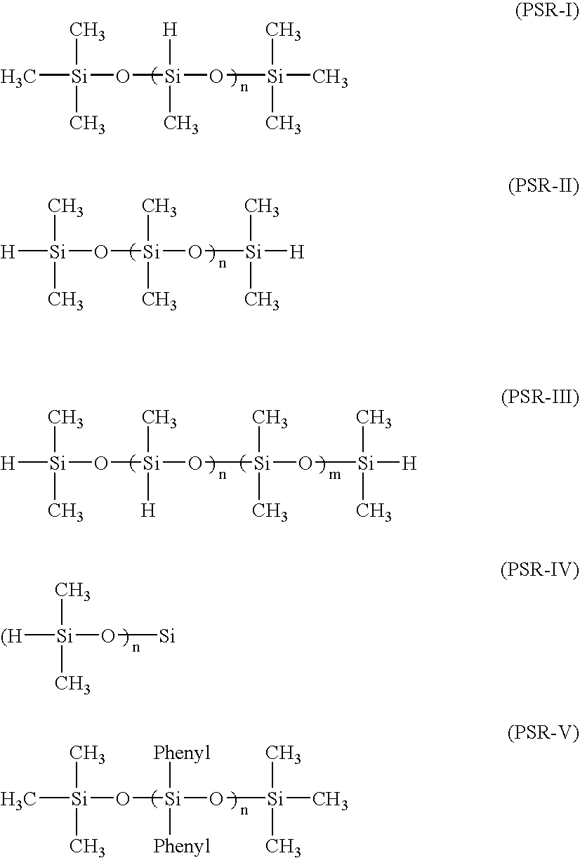
[0164]A two-layer lithographic printing plate precursor was prepared by applying the non-silicone non-crosslinked layer formulation Y to Substrate A and dried for 45 seconds at 135° C. to provide a dry coating weight of approximately 1.40 g / m2.

[0165]The silicone rubber layer formulation Z was then applied to this dried layer to provide a dry silicone rubber thickness of about 1.9 μm after curing at 140° C. for about 4 minutes.

[0166]Samples of the resulting non-ablative imageable element were imaged using a Kodak® Trendsetter SPECTRUM 800 at various imaging energies from 110 mJ / cm2 to 250 mJ / cm2 at 20 mJ / cm2 increments. The imaging file included 0-100% tints and 1 to 4 pixels wide lines. The imaged elements were then developed by wiping them with water to remove the silicone rubber layer and the upper portion of the non-silicone layer in the non-exposed regions, and the resulting printing plates were then inked and used for printing. From the printed impressions, it was apparent that...

invention examples 2 and 3

[0168]The imageable element described in Invention Example 1 was imaged as described therein at 130 mJ / cm2 but processed using either an aqueous solution of Tween® 80 nonionic surfactant (1 weight %) for Example 2, or an aqueous solution of Zonyl® FTS nonionic surfactant (1 weight %) for Example 3. In both instances, a suitable image was obtained that was then used for acceptable waterless printing (1-100% tints 200 lpi). The print run was stopped after 70,000 impressions.

invention example 4

[0169]An imageable element like that described in Invention Example 1, but without the crosslinked silicone rubber layer, was cut into 5 pieces (each 10×10 cm) and weighed. The non-silicone, non-crosslinked layer was then removed from each by immersing and rubbing them with Developer 956 (Eastman Kodak Company). Then, the remaining aluminum substrate from each piece was weighed to calculate the amount of non-silicone, non-crosslinked layer that had been removed in the developer.

[0170]The same process was carried out on two sets of five samples of the same element that had been imaged and processed according to the present invention. Element A and Element B in the following Table represent the two sets. The non-silicone, non-crosslinked layer was removed in the developer and the remaining aluminum substrate was weighed. We then compared of the removed non-silicone, non-crosslinked layer from the non-imaged element to that removed from the imaged element. We found that the difference ...


PUM

PropertyMeasurementUnit
Fractionaaaaaaaaaa
Fractionaaaaaaaaaa
Percent by massaaaaaaaaaa

Abstract

An imageable element can be imaged using non-ablative processes. This element has a non-silicone, non-crosslinked layer contiguous to and under an ink-repelling crosslinked silicone rubber layer. These elements can be used for providing lithographic printing plates useful for waterless printing (no fountain solution). Processing after imaging is relatively simple with either water or an aqueous solution consisting essentially of a surfactant or mechanical means to remove the crosslinked silicone rubber layer and a minor portion of the non-silicone, non-crosslinked layer in the imaged regions.

Description

FIELD OF THE INVENTION[0001]This invention provides an improved non-ablative imageable element that can be imaged without ablation and then developed with a simple aqueous solution and used for “waterless” printing. This invention also provides a method of using such non-ablative imageable elements.BACKGROUND OF THE INVENTION[0002]In conventional or “wet” lithographic printing, ink receptive regions, known as image areas, are generated on a hydrophilic surface. When the surface is moistened with water and ink is applied, the hydrophilic regions retain the water and repel the ink, and the ink receptive regions accept the ink and repel the water. The ink is transferred to the surface of a material upon which the image is to be reproduced. For example, the ink can be first transferred to an intermediate blanket that in turn is used to transfer the ink to the surface of the material upon which the image is to be reproduced.[0003]Waterless printing plates have been known and used since 1...

Claims


Application Information

Patent Timeline
IPC IPC(8): G03F7/004G03F7/26
CPCB41C1/1016B41C2201/02B41C2201/14B41C2210/24B41C2210/08B41C2210/22B41C2210/02B41C2210/16
Inventor MELAMED, OPHIRAHUANG, JIANBINGKONSTANTINI, EFRAT
Owner EASTMAN KODAK CO
Why Eureka
Try Eureka