Low-offset automatic compensation circuit

An automatic compensation and circuit technology, applied in improving amplifiers to reduce temperature/power voltage changes, DC-coupled DC amplifiers, differential amplifiers, etc., can solve problems such as heavy workload and complex signal components, and achieve fast response and simple circuit , Reduce the effect of debugging workload

Inactive Publication Date: 2013-03-13
KUNSHAN BEIJI PHOTOELECTRON SCI & TECH
View PDF4 Cites 7 Cited by
  • Summary
  • Abstract
  • Description
  • Claims
  • Application Information

AI Technical Summary

Problems solved by technology

[0002] Modern mechanical diagnostic systems collect more and more types of signals, and the signal components are more and more complex. There will be many amplifier circuits on one acquisition board, and the initial debugging will appear to be a lot of work.

Method used


Image

  • Low-offset automatic compensation circuit

Examples


Embodiment Construction

[0011] The present invention will be further described below in conjunction with accompanying drawing.

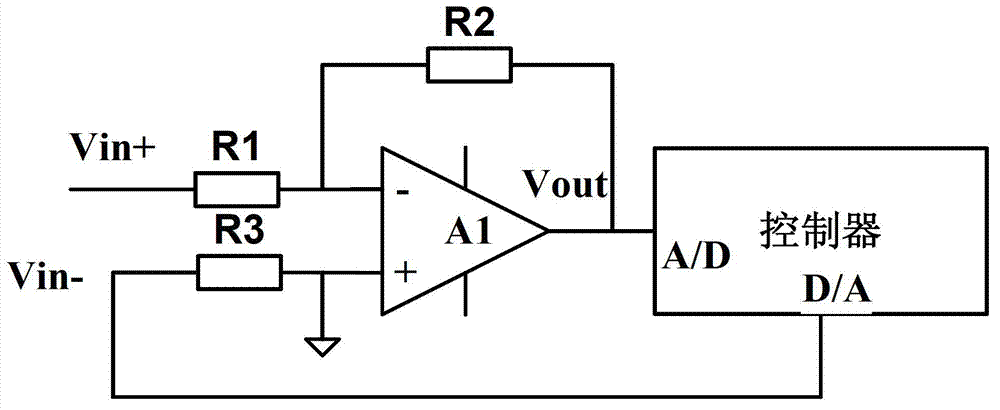
[0012] Please refer to figure 1 , a low offset automatic compensation circuit is shown in the figure, including operational amplifier LM385, resistors R1~R3 ​​and controller AT89C196;

[0013] The positive input terminal of LM385 is connected to the reference ground level, and connected to the D / A pin of AT89C196 through resistor R3, and connected to the negative input signal Vin-, and the negative input terminal of LM385 is connected in series with the positive input signal terminal Vin+. R1, resistor R2 connected in series between the inverting input terminal and the output terminal of LM385, the output voltage signal of the output terminal of LM385 is connected with the A / D pin of AT89C196.

[0014] Resistor R1=R3=1k, resistor R2=10k.

[0015] LM385 and resistors R1 and R2 form an inverting amplifier. The levels of the positive and negative input terminals of LM385 are...


PUM


Abstract

The invention discloses a low-offset automatic compensation circuit which comprises a positive input signal end Vin<+>, a negative input signal end Vin<->, an operational amplifier A1, resistors of R1 to R3 and a controller. The low-offset automatic compensation circuit disclosed by the invention is used for realizing a method for automatically compensating and operationally amplifying low-offset voltage and has the characteristics of high sensitivity, high response and simple circuit.

Description

technical field [0001] The invention belongs to the field of mechanical diagnosis, in particular to a low offset automatic compensation circuit in data acquisition of a diagnosis system. Background technique [0002] Modern mechanical diagnostic systems collect more and more types of signals, and the signal components are more and more complex. There will be many amplifier circuits on one acquisition board, and the initial debugging seems to be a lot of work. A circuit is needed to automatically compensate the offset voltage and reduce the debugging workload. Contents of the invention [0003] The purpose of the present invention is to provide a low offset automatic compensation circuit for reducing the debugging workload in the data acquisition of the diagnosis system. [0004] The technical solution for achieving the above purpose is: a low offset automatic compensation circuit, including a positive input signal terminal Vin+, a negative input signal terminal Vin-, an o...

Claims


Application Information

Patent Timeline
Patent Type & Authority Applications(China)
IPC IPC(8): H03F3/45H03F1/30
Inventor 杨向萍
Owner KUNSHAN BEIJI PHOTOELECTRON SCI & TECH
Why Eureka
Try Eureka