
Rotor spinning machine

A technology of air spinning machine and spinning cup, which is applied to spinning machine, open-end spinning machine, continuous winding spinning machine, etc. It can solve the problems of complex manpower, intensive production, and inability to maximize production. , to achieve the effect of increasing productivity

Active Publication Date: 2013-03-20
SAURER GERMANY GMBH & CO KG
View PDF7 Cites 8 Cited by
  • Summary
  • Abstract
  • Description
  • Claims
  • Application Information

AI Technical Summary

Problems solved by technology

Completing trials is complex and labor intensive
Maybe not even maximizing production

Method used


Image

  • Rotor spinning machine
  • Rotor spinning machine
  • Rotor spinning machine

Examples


Embodiment Construction

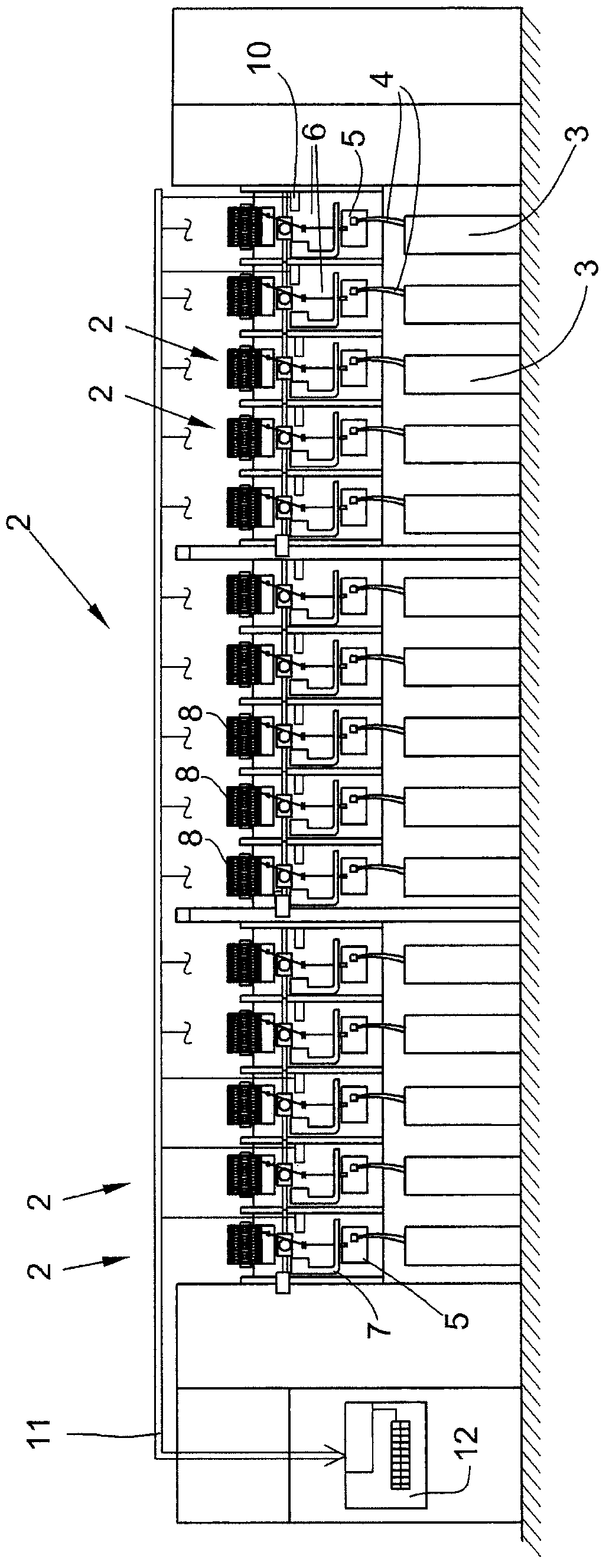
[0026] figure 1 An air spinning machine 1 with multiple stations 2 is shown. At each station 2, the fiber sliver 4 prepared in the fiber spool 3 is supplied to the air spinning device 5, and the spun yarn 6 is drawn from the air spinning device 5 and wound into a cross Winding bobbin 8. Each of these stations 2 has a station computer 10 which controls the operating mechanism of the station 2 and is connected to the central control unit 12 via a bus system 11.

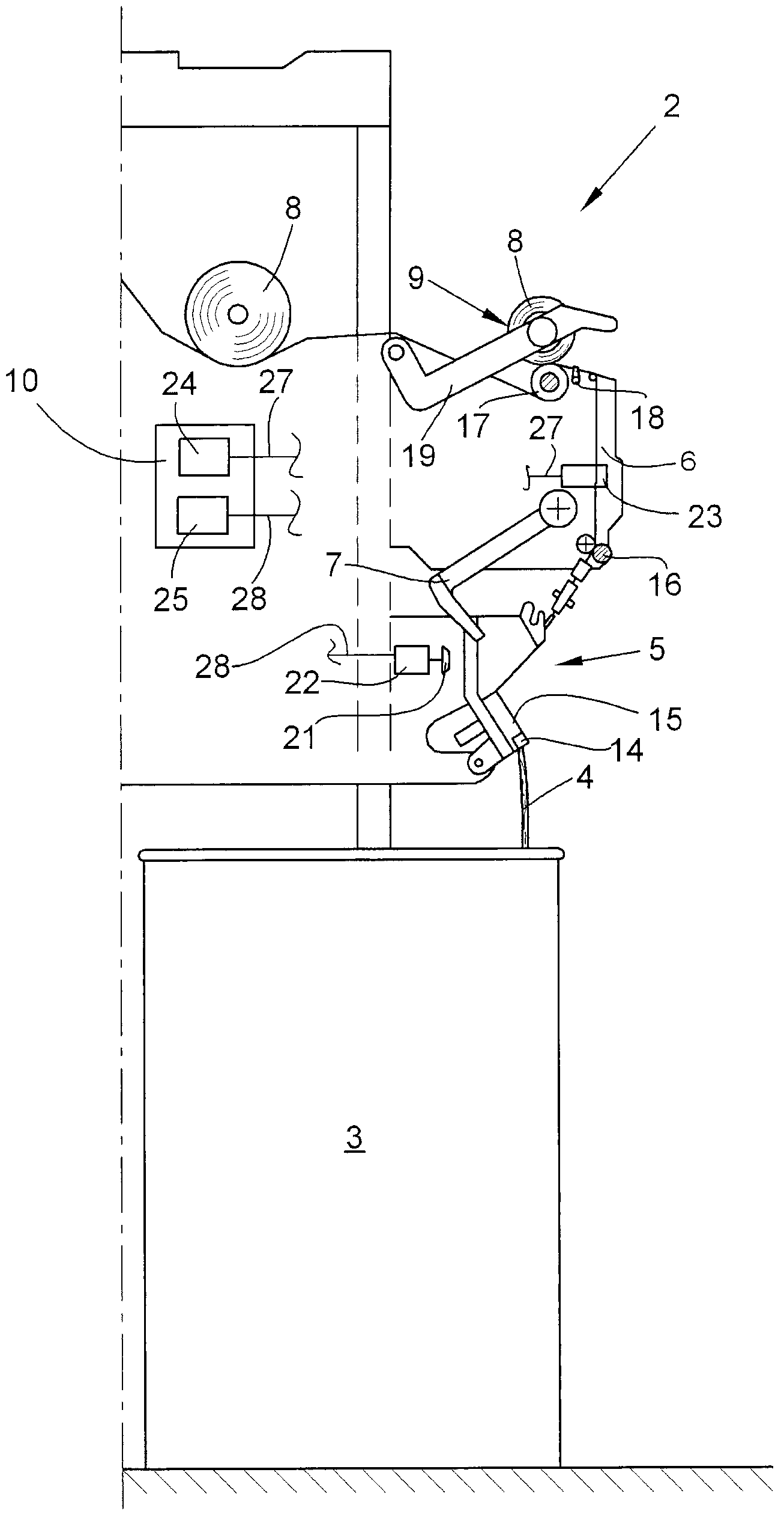
[0027] figure 2 A side view of the air spinning machine 1 is shown. Because the two sides of the machine 1 are symmetrical, so in figure 2 Only the side with station 2 is shown in. The station 2 is equipped with a spinning device 5 and a winding mechanism 9. In the air spinning device 5, the fiber sliver 4 fed into the fiber spool 3 is spun into a spun yarn 9 by means of a spinning cup 21, and the spun yarn is wound into a yarn on the winding mechanism 4 Line bobbin 8. In order to drive the spinning cup 21, a separa...


PUM


Abstract

The invention relates to a rotor spinning machine (1) which comprises several work stations (2), each having a spinning rotor (21). A drive unit (22) performs variable-speed drive of the spinning rotor. A measuring unit (23) detects the thread breaks, and an evaluation unit (24) detects the yarn breakage rate. According to the invention, the rotor spinning machine comprises a control unit (25) which is configured to be used for adjusting the speed of spinning rotors (21) automatically in dependence on the respectively determined yarn breakage rate, and thus controlling the yarn breakage rate, so that the yarn breakage rate is below a predetermined maximum yarn breakage rate.

Description

Technical field [0001] The invention relates to an air spinning machine, which has a plurality of workstations each with a spinning cup, a driving device for driving the spinning cup with a variable speed, a measuring mechanism for detecting yarn breakage, and a Analysis mechanism for yarn breakage rate. Background technique [0002] The air spinning machine has multiple stations. At each station, the fiber sliver prepared in the fiber spool is supplied to the spinning device. The spinning device includes a spinning cup, which rotates at high speed in a rotor housing closed by a cover plate and bearing a negative pressure during the spinning process. The spun yarn is drawn out from the spinning device by the drawing mechanism and wound into a cross-wound bobbin. [0003] German utility model patent application publication DE 7148737U discloses a drive motor, which drives a drive belt common to all spinning cups through a stepless adjustment transmission device, and the drive of ...

Claims


Application Information

Patent Timeline
Patent Type & Authority Applications(China)
IPC IPC(8): D01H4/44D01H13/32
CPCD01H4/44
Inventor K·M·鲍尔勒泰·麦克
Owner SAURER GERMANY GMBH & CO KG
Learn More