
Reinforced concrete inner support with pre-stressed loaders for supporting foundation pit

A reinforced concrete and foundation pit support technology, which is applied in the direction of basic structure engineering, excavation, construction, etc., can solve the problems of reinforced concrete support such as prestressing, difficult control, large deformation of foundation pit, etc., to achieve large span and large support rigidity , The effect of controllable foundation pit deformation

Active Publication Date: 2013-03-20
SHANGHAI STRONG FOUND ENG
View PDF7 Cites 10 Cited by
  • Summary
  • Abstract
  • Description
  • Claims
  • Application Information

AI Technical Summary

Problems solved by technology

However, the existing reinforced concrete support is an integral pouring structure. After the construction is completed, the earth pressure changes on the outside of the foundation pit, so it is impossible to apply prestress to the reinforced concrete support, resulting in large deformation of the foundation pit, which is difficult to control

Method used


Image

  • Reinforced concrete inner support with pre-stressed loaders for supporting foundation pit
  • Reinforced concrete inner support with pre-stressed loaders for supporting foundation pit
  • Reinforced concrete inner support with pre-stressed loaders for supporting foundation pit

Examples


Embodiment 1

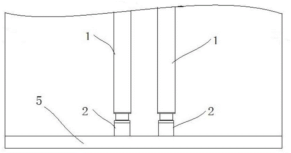
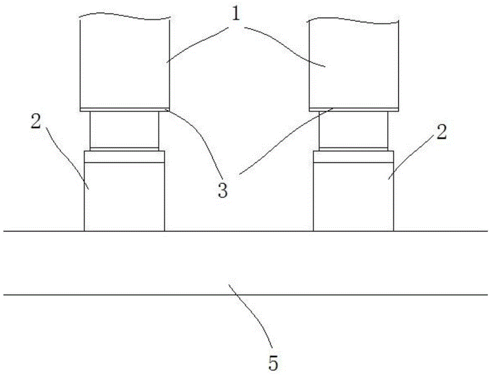
[0020] Embodiment 1, see figure 1 and figure 2 , shown in the figure is a foundation pit adopting the structure of reinforced concrete counter brace 1, and the counter brace 1 is a structure of two side by side, of course, a single or multiple counter brace 1 can also be set as required. It can be seen that when the earth pressure on the outside of the foundation pit changes, the prestress of the reinforced concrete brace 1 needs to be adjusted accordingly to offset the earth pressure on the outside of the foundation pit.

[0021] For this reason, at the connection between the end of the brace 1 and the purlin 5, a disconnected end face is provided, and a prestress loader 2 is arranged on each disconnected end face of the brace 1, and the prestress loader 2 One end is pushed against the disconnected end face of the brace 1, and the other end is pushed against the purlin 5. In order to facilitate the pressing of the loader 2, a steel plate 3 is provided on the end face of th...

Embodiment 2

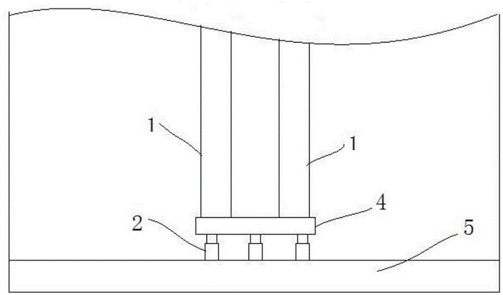
[0023] Example 2, see image 3 and Figure 4 , it can be seen that the reinforced concrete brace 1 is two side-by-side structures, and of course a single or multiple braces 1 can also be provided as required. At the connection between the end of the brace 1 and the purlin 5 , a disconnected end surface is provided for setting the prestress loader 2 . Specifically, a top plate 4 is provided at the end face of the brace 1, and a prestressed loader 2 is arranged between the top plates 4. There are a plurality of loaders 2, which are evenly distributed between the top plate 4 and the purlin 5. Purlin 5 and top plate 4 apply prestress, loader 2 directly applies prestress to one end of purlin to offset the earth pressure, and the other end transmits prestress to counter brace 1 through top plate 4 to be transferred to the purlin of the foundation pit to offset earth pressure. The purlin 5 is a steel concrete composite purlin.

[0024] The top plate 4 is a reinforced concrete str...


PUM


Abstract

The invention provides a reinforced concrete inner support with pre-stressed loaders for supporting a foundation pit. The reinforced concrete inner support comprises reinforced concrete supporting beams and reinforced concrete enclosing purlins, which are arranged in the foundation pit, wherein a plurality of pre-stressed loaders are arranged between the reinforced concrete supporting beams and the reinforced concrete enclosing purlins. The inner support is high in supporting rigidity and controllable in foundation pit deformation. The prestress applied to the reinforced concrete support can be adjusted at any time when the soil pressure of the side wall of the foundation pit is changed, so that the soil pressure of the side wall of the foundation pit is counteracted.

Description

technical field [0001] The invention relates to the technical field of civil engineering, in particular to an inner support structure for foundation pit support, and further relates to a reinforced concrete inner support for foundation pit support with a prestress loader. Background technique [0002] In the foundation pit support structure, the reinforced concrete support is often used in the commonly used supports of the internal support support structure. The reinforced concrete support has the advantages of simple construction and not being limited by the shape of the foundation pit. However, the existing reinforced concrete support is an integral pouring structure. After the construction is completed, the earth pressure changes on the outside of the foundation pit, so it is impossible to apply prestress to the reinforced concrete support, resulting in large deformation of the foundation pit and is difficult to control. Contents of the invention [0003] The technical ...

Claims


Application Information

Patent Timeline
Patent Type & Authority Applications(China)
IPC IPC(8): E02D17/02
Inventor 刘全林宋伟民陈伟宏毕平均
Owner SHANGHAI STRONG FOUND ENG
Learn More